
Click here for a YouTube Tutorial covering the features of Archimesh

Archimesh is an architectural design tool add-on for Blender that generates an array of architectural objects. This add-on must be enabled in preferences for it to become available in the 3D scene. Press F4 for the file context menu and open preferences.
Press F4 to open preferences

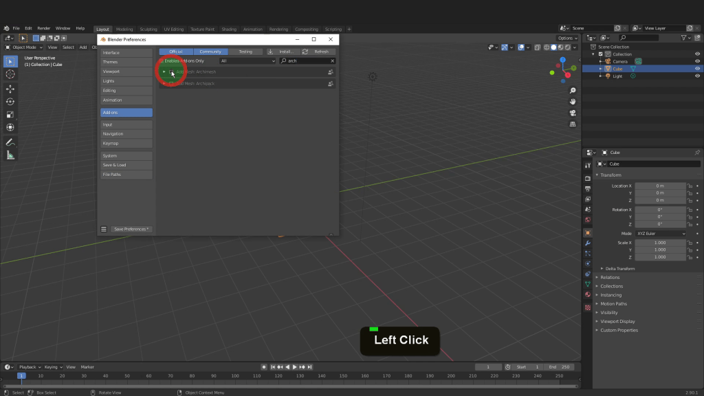
We can begin by opening the add-ons tab. In the search box up top start typing arc. Enable the Archimesh add-on by putting a check mark in the box.
Enabling the Add-on
Expand the add-on to get the location details. This add-on can be found in the 3D view from the add mesh menu or on the sidebar in the creates tab. We can close this by clicking the X here. Back in the 3D scene we can come to the add menu. In mesh you will find the list of Archimesh objects. The add-on will have more settings here on the sidebar. Press N to open and close the sidebar. Open the create tab and the add-on will be available here.
The Archimesh add-on located on the Sidebar

For a Detailed Course on Udemy check out my New Course Below
Take the CourseArchimesh provides a selection of parametric architectural elements that can be dragged and dropped into the scene. These elements get added to the scene at the position of the 3D cursor. The properties of these parametric object can be updated at any stage. However some objects such as cabinets, stairs and roof objects only has initial properties and cannot be adjusted after they are closed. Lets look at adding a room. In the scene I can select everything, press X and delete all. Press Shift + S and place the cursor back to world origin. Now click room. This gets added at the position of the 3D cursor standing upright and running along the X axis. This represents the first wall of the room and includes a base board. The room properties are now available to modify in the room area on the sidebar. The wall has a default measurement length of one metre a height of 2.4 metres and a wall thickness of zero. This Inverse check box will switch the direction the wall faces. Lets increase the number of walls to 4. New walls get added at 90 degrees to the preceding wall. Each wall is numbered and their length can be adjusted in the length field here. For the length of the first wall I can input 12, tab into the second field and input 8, input -12 in the third and -8 in the fourth. We could input zero in the fourth and then use the close wall option here and that will close the room off. Increase the height to 4. We can also give the wall a thickness of 0.3. Each wall has advanced options. In wall 2 In the drop down control the wall visibility, whether it has a base board or if the wall is hidden. Create a curved wall with the check box option. Here you can determine the centre and resolution of the wall. I can un-check curve. In the peak field input 1.925. This creates an apex and ready to take a roof. We can repeat that in wall 4 and input 1.925 and match the wall on the opposite end.
The Baseboard setting will add a baseboard to the wall with width and height properties. The length is automatically associated with its connected wall. The Wall Cover settings adds an exterior type cladding and options to control its placement, individual cover height and thickness.
The Room Properties

Each element is added with a default cycles material once this option is enabled here. In the materials tab the material is listed. Each has a colour assigned for viewport display down the bottom.
Cycles Material Setting

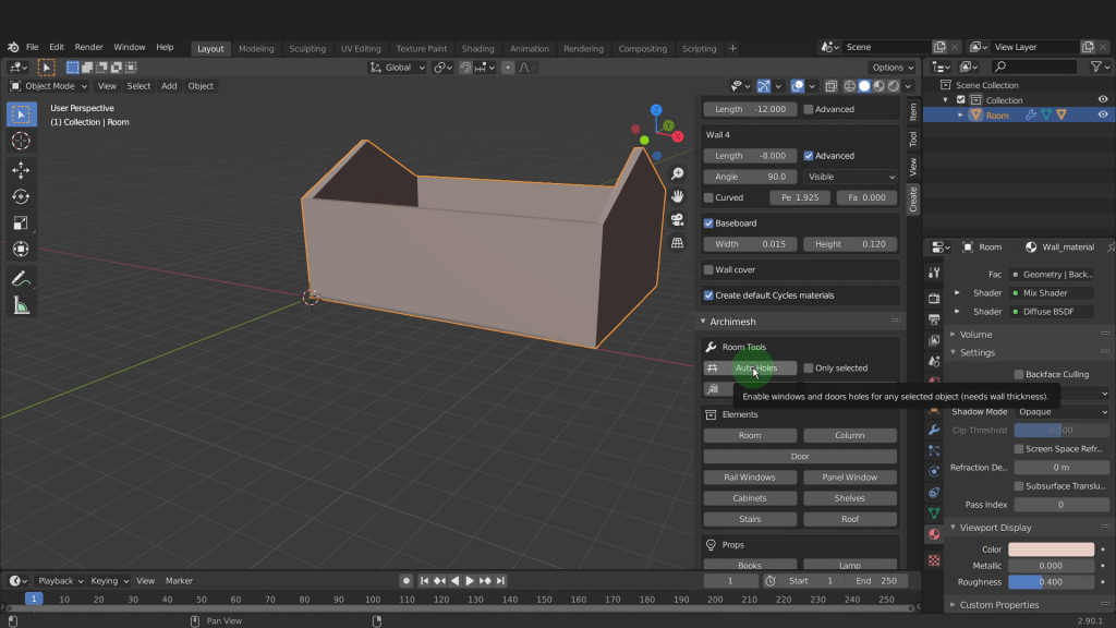
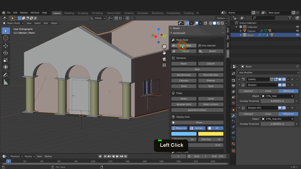
The Auto holes button relates to the room. This button will automatically creates a boolean operation to the wall when a door or window element has overlapped with a wall. We will take a look at that in a moment.
AutoHoles Button
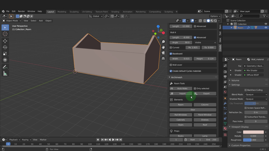
There are Import and Export options available that allow you to export your custom room properties stored in a (.dat)file. All room properties such as the height, width the base board options are stored and you can easily import them to your next project. To export select the room you want to export, press the export button and choose a location, give it a file name with extension (.dat)
To import your saved .dat file add a room to the scene, select import, navigate to where you stored the file. Select it and add into the scene. The room you added will get updated from the properties data from inside the .dat file.
Import & Export Settings
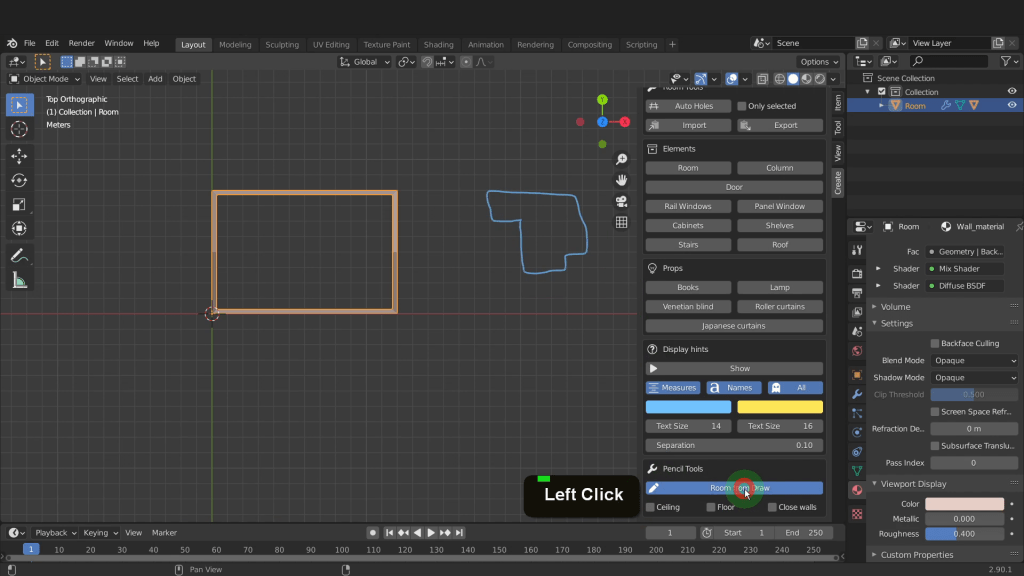
The final Room options on the Archimesh add-on are below here. Room from draw in pencil tools creates a room using the grease pencil. To demonstrate I’ll go into a top orthographic view. Press and hold D for grease pencil, press and hold the left mouse button and start drawing. Release to finished drawing. Put a check mark in ceiling, floor or closed walls to enable those options. Select room from draw and your grease pencil lines transform into actual mesh geometry that can be modified in the room properties.
Room From Draw
I can drag select everything and press X and delete it.
Lets use the column option from the add-on. First we need to place the 3D cursor so the column gets added at the same Z location as the wall. I can select the wall and tab into edit mode. Select the bottom Vertex. Press Shift + S and choose cursor to selected. Now tab back to object mode. In the view tab in 3D cursor move this forward along the x-axis. That way when it gets added we can see the changes we make. Now on the add-on click column and add that into the scene.
The column properties become available down here on the bottom left of the screen. The first option is to switch between circular or rectangle. We can leave this set to circular. Here you can control the height, width, depth and radius. I can increase the radius to 0.3. Increase the height to 2.43. There are options here for top and bottom rectangular, circular and we can enable all of these. Increase the rectangle base to 0.8 top and bottom. Enable the top arch. In the radio field reduce this to 0.95 so these reduce in size and match the width of the building. In the thickness field I can increase this to 0.24. Put a check mark in create array of elements. Increase the X count to 4. That’s it for these properties. Now these are initial options and only temporary. If we click away and preform another task we can no longer edit these columns. If you click away and loose the properties while editing you can press F9 and bring them back. If after you want to make changes you can add another column and it will take on the properties of the last one created.
Column Properties

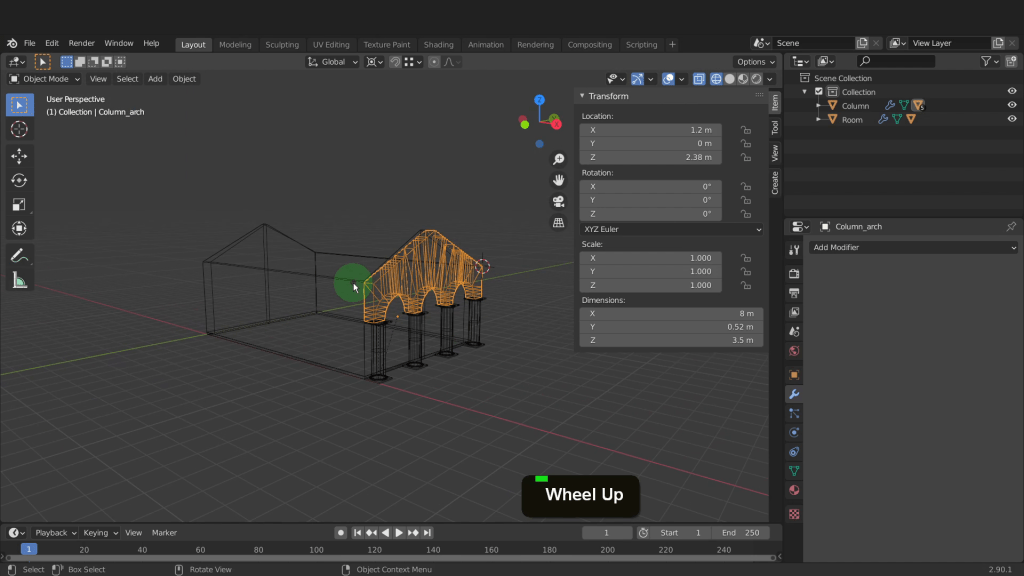
This first column is the parent object so lets rotate all these and position them. Press R Z input 90 and enter. Press Numpad 1 for front view. Open the item tab. Drag these back in the X location and align to the wall. Press Numpad 3 for side view and in the Y location click and centre these up on the wall.
Now that these objects are permanent we can modify them. Select the arch object. In the modifiers tab there are two modifiers on this object. The first is a mirror and the second an array. Hover on the first and press Ctrl + A to apply and repeat that for the second. Now back in the scene press Z and switch to wireframe. Tab into edit mode now. In the snap menu we can switch to vertex. Drag select all the top row of vertices. Press G, Z press and hold the Ctrl to activate snap and snap up to the top of the wall. Drag select the left side of vertices. Press G, Y press and hold Ctrl and snap to the endpoint. Drag select the opposite side and repeat. Select the centre Vertices and drag these up in the Z and snap to the height. Select this corner vertex. We can use this as the pivot point. Press Shift + S and choose cursor to selected. Drag the top set of vertices on the left. Press the period key and switch to the 3D cursor. Press R and rotate these around to match up with the wall slope.
Arch Rotation
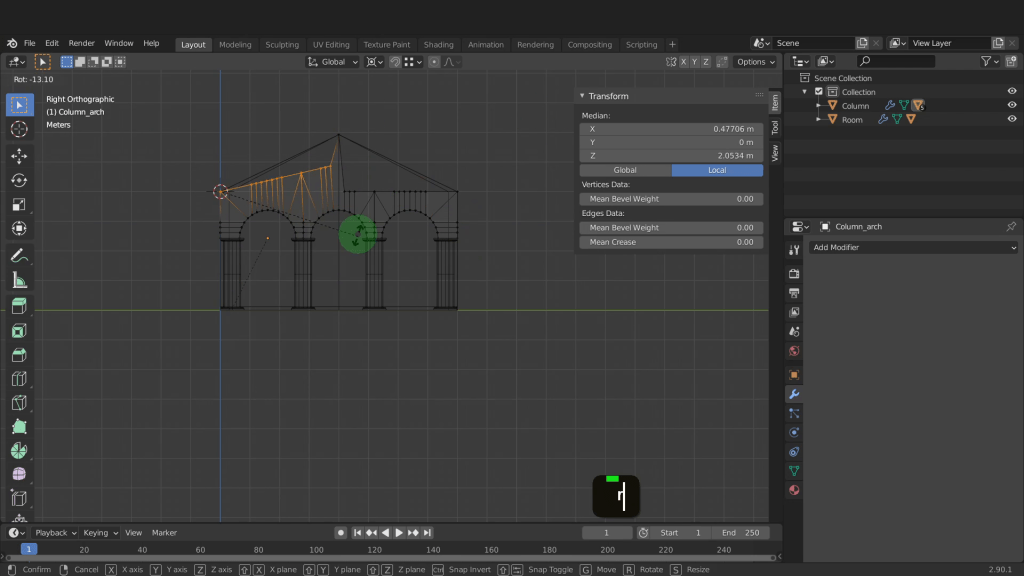
Press the Shift key to get finer increments and left click to confirm. Select the vertex on the opposite side and put the cursor to selected. Drag select the right side vertices. Rotate these up also and match the slope. Press Numpad 1 and zoom in here. Drag select these vertices on the back. Press G, X and snap back to the front of the wall. Now tab back to object mode.
Modified Arch Object
Let’s add a door to the front wall. Select the wall and tab into edit mode. Select the front two vertices on the bottom. Press Shift + S and put the cursor to selected. Now tab back to object mode. Let’s click door on the add-on. This gets added at the position of the 3D cursor. The properties relating to this appear on the add-on. First we can input 90 into rotation. There are properties to adjust the door width, height and frame size. In the drop down change the model from one of the presets. The handle type can also be changed in the handle drop down. Lets increase the frame width to 1.7. Tab into the frame height and input 2.5. input 0.4 for the frame thickness and 0.2 for the frame size. Press Z and switch back to solid shading.
Door Settings

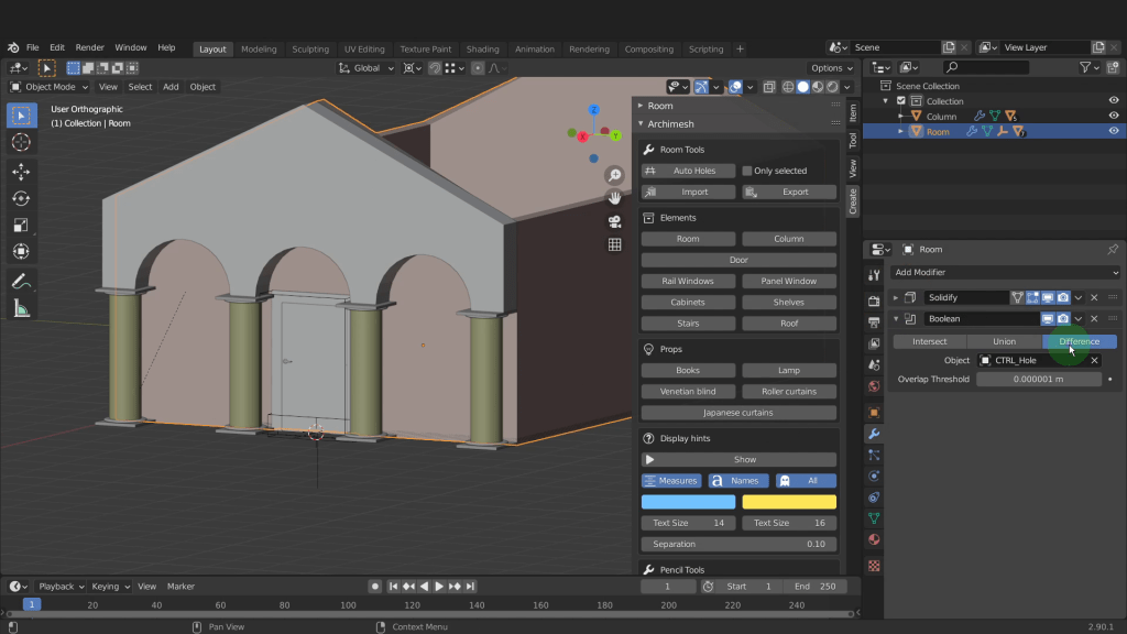
The door unit is made up of 7 separate objects. The door consists of the frame, the door panel, and an inside and outside handle. The door panel is constrained on all axis except the Z rotation as we can see here in the transform panel. The padlock icon indicates what axes are locked. That way when you press R the door will only rotate on the Z axis. Clicking the padlock will unlock or lock that axis. This is to protect against accidental movement or rotation and misalignment from the door. The next piece of the door is the Ctrl_hole object. This is the first cube shaped object displayed as wire. This is used to subtract the cube shape from whatever the door gets inserted into. This results in an opening being created and we can take a look at that in a moment. This second cube shape on the base that is displayed as wire is used to subtract the baseboard if the wall has one enabled. The next object is the empty plain axis object. This is named Door_Group. The Door frame and Ctrl_hole object are parented to this empty object. Press G with the empty selected and the door unit will follow along. This makes the unit easy to manage. We can see the relationships in the object properties tab here and in the relationship tab. If you select the door frame. In the parent field the Door group is listed. If you select the Door panel the Door frame is listed as the parent. The handles are parented to the door panel. Select the empty and drag this so the door centres on the wall. This will get it ready to create the subtraction. Select the wall now and in the create tab click auto holes. This will add a boolean modifier to the wall and use the Ctrl_hole object to subtract the cube shape. In the modifiers tab beneath the solidify modifier is the boolean modifier. This has the operation set to difference and the Ctrl+hole object set at the object. This modifier is forming that hole in the wall based on these settings. The position of the door can be adjusted and the modifier will update the subtraction.
Boolean Modifier
The next object on the add-on are two windows styles. The rail and panel. First press the period key and switch back to the medium point. Let’s now add the rail window. Similar to the door the window unit consists of multiple objects all parented to this empty. Select the empty and drag this cross on Y axis and left click. Drag this back on the X and position. Drag it up in the Z and position it here.
Rail Window
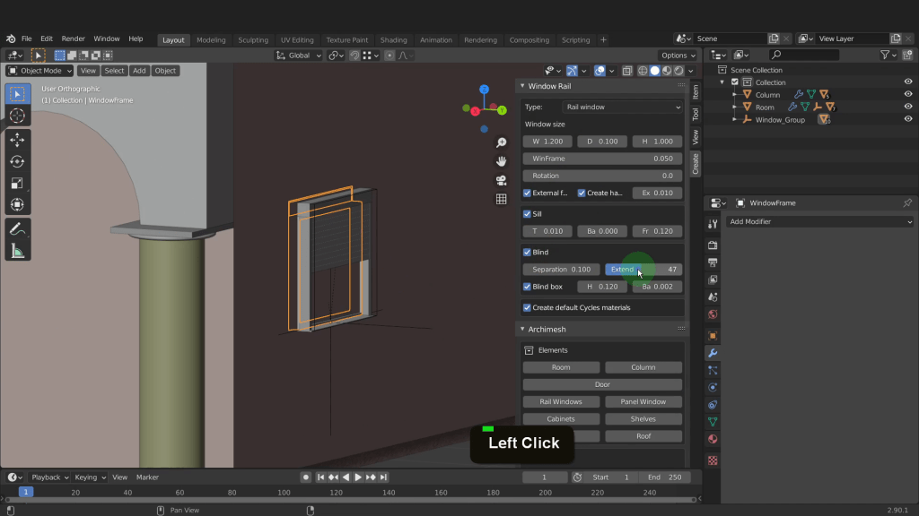
Select the wall and click Autoholes and create the subtraction. Select the frame of the window for the properties to become available. Here we have similar properties to the window to adjust the width and height. Enable this blind to creates an external blind. This can then be extended up or down using this value here.
Subtraction
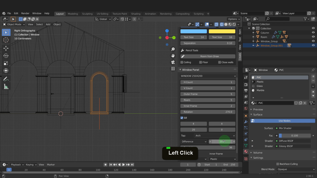
Lets add a panel window. The properties of for this window become available below. In the drop down select one of the panel styles available. The window styles allow for a maximum of eight horizontal sections and five vertical. Each section can be adjusted to the required dimension. The top of the window can be inclined, arched, flat or triangle allowing for a multitude of shapes to fit any design. The panel window also has an option for a sill with adjustable dimensions.
The frame and inner frame can be assigned a different material from the drop down. Each window will have material slots added the a material added to each slot. The glass part of the window has a glass material assigned to these faces. Select the empty and press Numpad 3 for side view. Switch to wireframe shading. Now drag the window across in the Y axis and centre this up on the two columns. Select the frame now. In the rotation field input 270 and rotate this to face forward. We can now make some modifications to the window. Reduce the H count to 1 so this has only one panel. Increase the width to 104 down the bottom here. Increase the height to 254. Change the top to be arch from the drop down menu here. Increase the difference to form the full round. Select the empty and drag this up. Drag select all of this and press Shift + D and drag across and line up on the opposite side. Position that there and left click. Switch back to solid view and select the wall. On the add-on click auto holes.
Panel Window
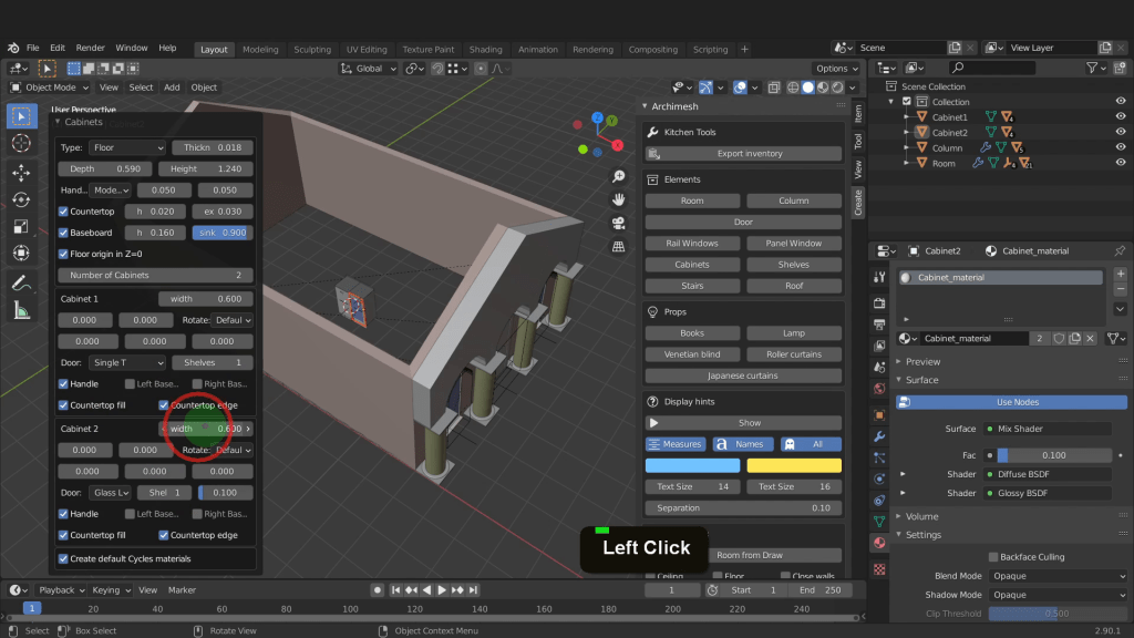
The next object are cabinets. In the view tab I can move the 3D cursor back along the X axis and Y axis so these get added inside the building. Switch back to the create tab now. I can click cabinets and add one in. The initial cabinet properties become available below here. These are temporarily and will disappear once you click away. Select the type to be floor or wall from the drop down menu. Here you have settings to control the cabinet dimensions. Control the number of units. Then change these cabinets sizes, rotation, position and select a door or drawer type for each one. These options allow for a wide range of customisation to the cabinets. Just remember once you click away from the cabinet these properties are no longer be available to modify.
Cabinet properties
Lets reposition the 3D cursor. Now back in the Archimesh add-on add a shelve. Much like the cabinet object shelves have similar properties. These properties are only available for the initial creation. The shelve object has an array modifier available. Each shelve unit created with the array modifier can be individually modified for a different style and dimension.
Shelf properties

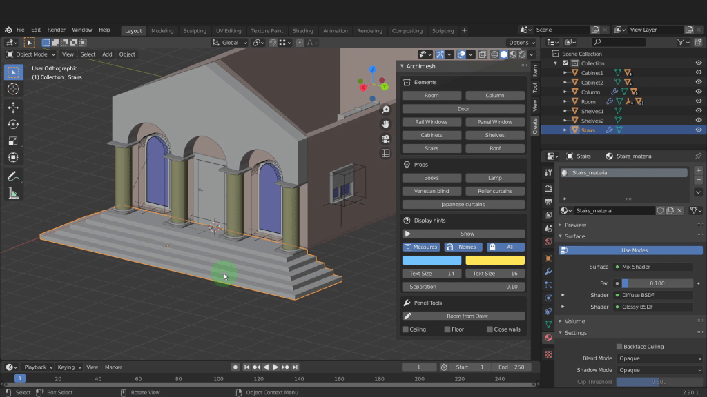
Next we have the stairs object. Let’s select the building and tab in here. Select the front two vertices on the bottom of the building. Press Shift + S and put the cursor to selected. Tab back to object mode now and on the add-on click to add a stairs. We can make a couple of modifications to this. The model we can leave at rectangle. Increase the number of steps to 5. Change the width to 8. Increase the depth to 0.36. Check on variable width and input 4.3 for that value. That way the side thread width will match loser to the front. We can rotate this. Press R Z input 90 and enter. Press Numpad 1 for front view. Drag this forward along the X axis. Now snap this back to the front of the column. I can rotate around. Now that this has been created lets modify it in edit mode. Switch to wireframe shading. Drag select all the side vertices on the edge of all these steps. We can select only what we need to extrude back to finish forming the steps. Press 2 for edge selection now. Now starting with the bottom step select all the back edges of each step all along here. This top edge is the active edge. In the snap menu switch to active here. That way we can snap to the active edge. Press E, X and snap to the wall. Press C and deselect the top edges. Now snap these into the wall. Repeat that down along and snap each step into the wall and finish off that step. The active part setting can be really useful in situations like this. Now drag select all the end vertices. Make the top vertex active. Press G, Y and snap to the outside corner of the wall. Select it all and snap down in the Z to the base of the column. We can tab back and switch back to solid shading.
Step Modified and in Position
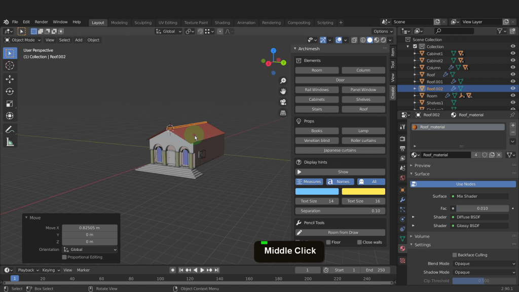
Let’s look at adding a roof to the building. First select the wall and Tab into edit mode. Select the Vertex at the back. Press Shift + S and put the cursor to selected. Now I can tab back to object mode. In the item tab lets update the position of the 3D cursor so the roof overhangs after it gets created. I can adjust this to -.5 in the X -.4 in the Y and 3.9 in the Z. Now switch back to the create tab. Click roof to create it. In the properties there are different styles to choose from. I can input 79 in the X, 11 in the Y. Increase the roof slope to whatever suits. I my case that is 25.8. Press Numpad 3 and take a look at the slope. Press G and move this into position. Select the wall now and tab into edit mode. Select the front vertex. Press Shift + S and put the cursor at selected. Tab back now and select the roof. Right click and set the origin to be at the 3D cursor. That will allow us mirror this roof to the opposite side. Press Shift + D to duplicate and right click. Press Ctrl + M for the mirror command. Input Y for the axis and press enter to confirm. In the item tab adjust the X rotation to -align this to the wall of the building. To cap this off with a ridge tile. Make sure the cursor is up top. Add another roof. Change the model number to 2. Reduce the X to 1 and increase the Y to 35. Increase the tile thickness to 0.120. input zero for the slope. Press R, Z input 90 and enter. Zoom in and move this centre of the roof. Press Numpad 1 and move this to be centre along the X axis.
Roof Object
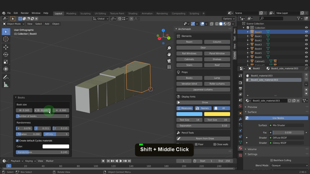
In the props section of the Archimesh tab you’ll find the remaining objects. These include Books, Lamps, Venetian Blind, Roller Curtains, and Japanese Curtains. This element gets added to the scene as a row of twenty books up to a maximum of one hundred. Use the dimension properties to control the size of the books. This element has a very useful feature that helps randomise your book shelf. Change the randomness sliders of the x, y, z and rotation to get a more realistic looking array of books on your book shelf.
Books
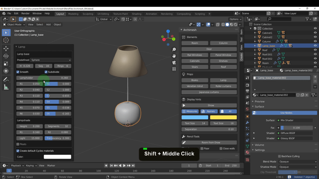
The lamp lets you choose from four default designs. Or get creative and design your own with loads of control over every segment of the lamp. The properties also allow full control of the lamp shade with or without pleats.
Lamp
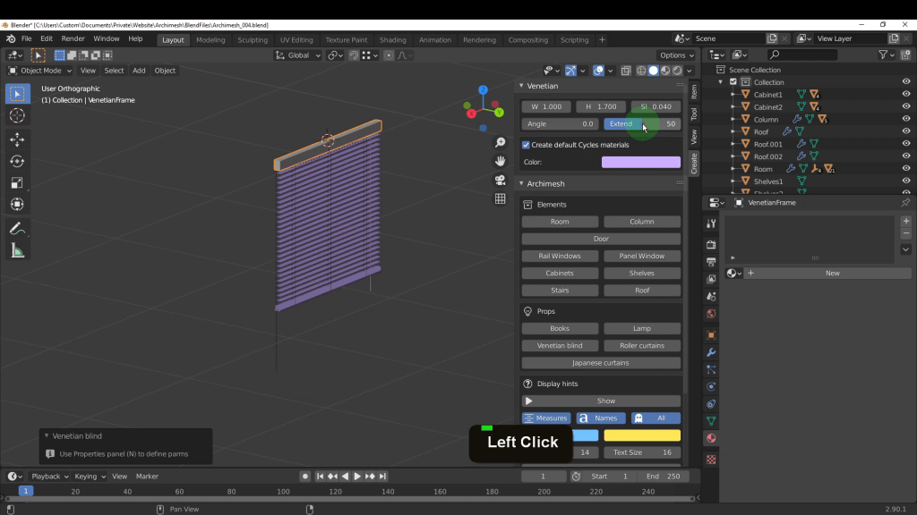
The Venetian Blind allow you easily control the dimensions or adjust the angle to open or close the blind.
Venetian Blind
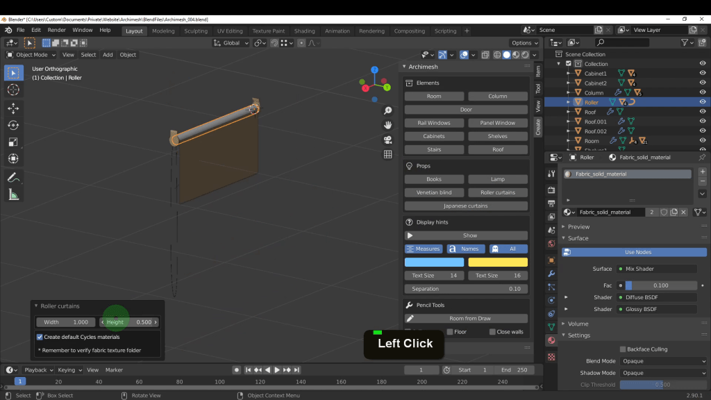
The roller curtains have similar properties allowing you adjust the width and length it is extended.
Roller curtains
The Japanese Curtains properties lets you adjust the dimensions, number of rails and panels and the position of each.
Japanese Curtains

Finally we have the display hints. These will display the dimensions and name of an Archimesh element. The properties lets you adjust the size, colour and placement of the text. If you change the size of a wall for example the dimension will update dynamically.
Display hints

I downloaded and added textures from https://texturehaven.com/textures/
The Add-on Dynamic Sky was used to light the scene.
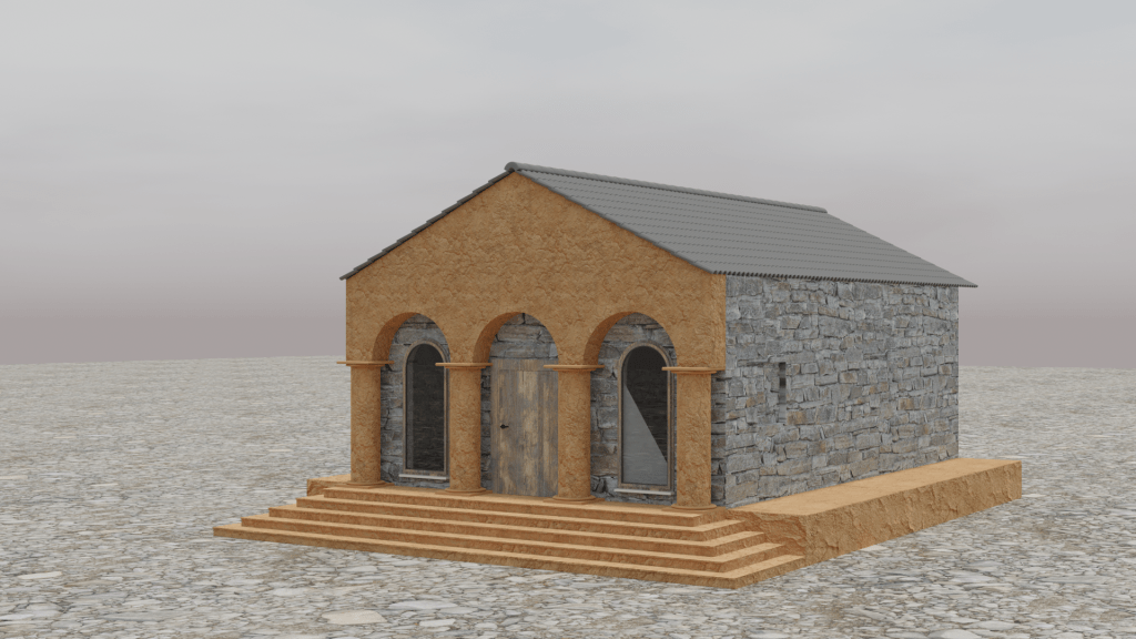
That was a look at the Archimesh add-on for Blender hope you enjoyed it.
Take the Course