
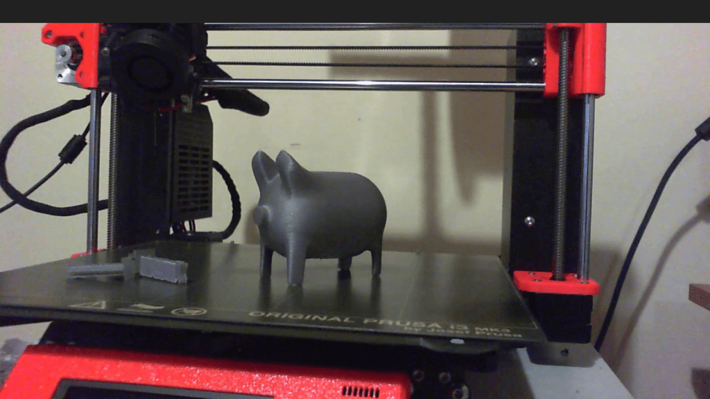
In the following post I work through the process of modelling this piggy bank in Blender for printing on a Prusa 3D printer. Watch the video here.
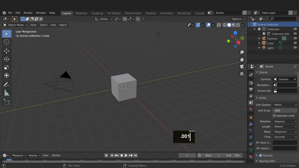
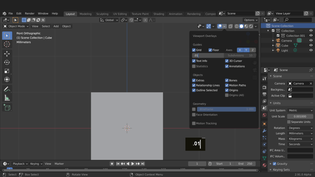
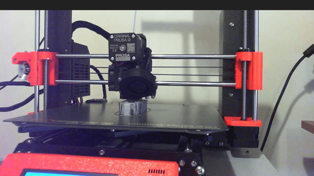
I’ll be using a Prusa printer to print the model. With all projects its a good idea to have the unit system set up before any modelling is done. On the left of the scene are the scene properties with an area for units. By default Blender begins with the unit system set to metric and the unit scale set to 1. Whether you want your 3D models for print, games, architecture or animation. Modelling using real world scale is kind of fundamental when yo want to design accurately. When working with small scale 3D printed models working in millimetre will be more accurate. Another benefit is to match the 3D printing software or service you are exporting to. You can always re scale and align the models later but setting things up first can avoid issues in the long run. To set Blender to millimetre you only need to change the unit scale to 0.001. Watch the full course here.
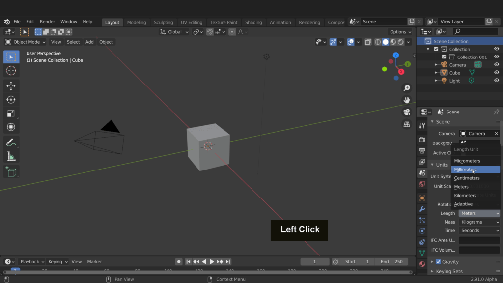
The scene updates to reflect the changes. Any model created in the file now will use this new scale. Also the slicer software used will read the model as millimetre on import. The final setting we can change here is the length setting. Here we can change this to millimetre.
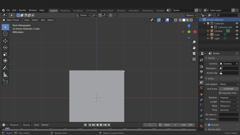
This will allow us input dimensions in millimetre. It will also display all dimensions in millimetre. Back in the scene press Numpad 1 for front view and Numpad 5 for orthographic. The grid is now divided into blocks measuring 1mm. We can see this as the cube is 2mm in length and there are two grid divisions equal to its length.
We can increase the number of grid divisions from the overlays tab by reducing this scale. Entering a value of 0.1 will result in the grid reducing with each millimetre equalling 10 grid divisions.
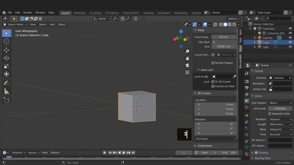
In the snap menu make sure the snap to is set to increment. Now back in the scene press G to move, press and hold Ctrl to activate snap, and the cube will snap in increments of 0.1 millimetres. This will help you achieve very accurate results when modelling. I can right click to cancel move. I can press and hold the middle mouse button and rotate around in the viewport. One setting that needs to be updated because of the changes we made to the scene scale and that is the camera clipping distance. Open the sidebar with the short cut key N. In the view tab increase the end clip to 10000mm. The end clip is how far away the camera can view an object before its clipped. The start clip can be set to 3mm. The start clip is how close you can get to an object before the camera clips the view. I find 3mm works well here.
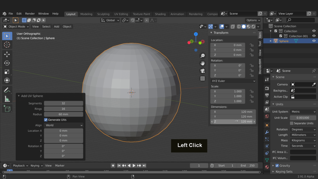
That’s the scene setup and we can now look at modelling. Press A to select everything and press delete. Press Shift + A and from mesh add a UV sphere.

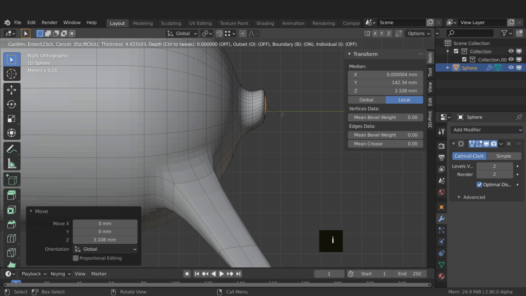
In the sphere properties change the radius to 60mm.

Press the home key to frame all and bring the sphere into view. Open the item tab on the sidebar and check the dimensions are correct. This should read 120 in the X, Y and Z dimension fields.
We need to rotate the sphere and have the top facing forward. Press R to rotate, X to rotate around the X axis, input 90 for the amount and press enter to confirm. Press Ctrl + A and apply that non-uniform rotation.
Press the Tab key and enter edit mode. Press 3 to switch the mesh selection type to face. Press Alt + A to deselect all faces. Press C for circle select. Using this selection type we can paint select the faces we need selected.

Right click to exit circle select. Now press E, input 10 and press enter to confirm.
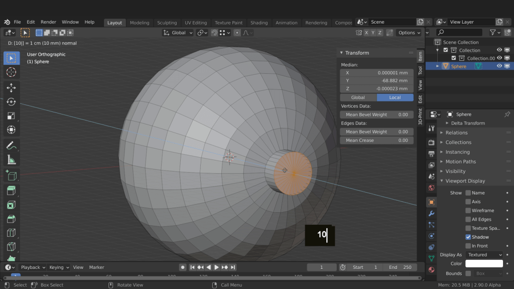
Press 2 and change selection type to edge selection. Press and hold the Alt key and left click to select this edge here. Press Ctrl + B and add a bevel. input 0.5 and press enter. This will soften down the edge.

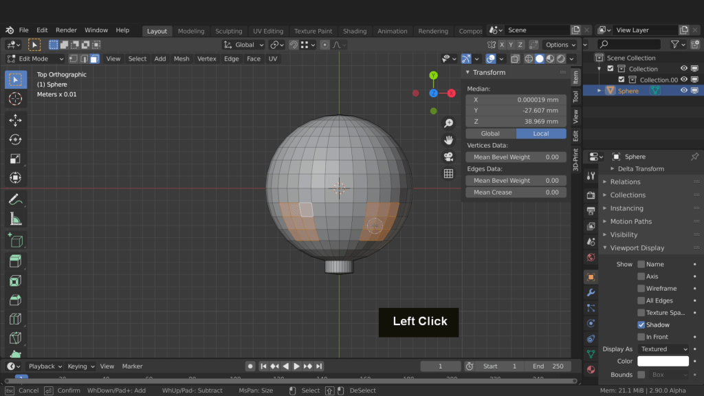
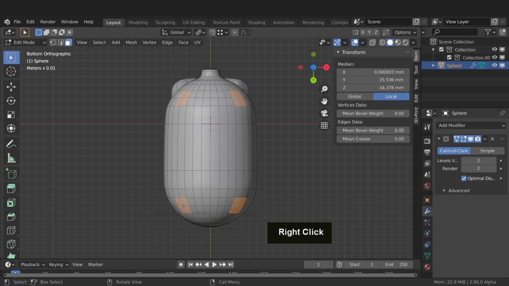
Press Numpad 7 for top view. Press 3 for face selection. Select these 9 faces each side. These will be used to form the ears.
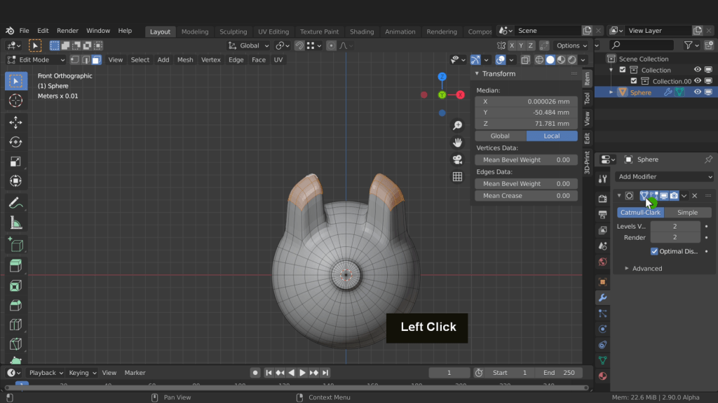
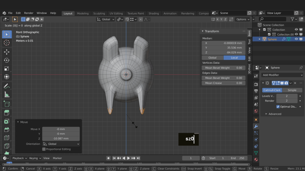
Press Numpad 1 for front view. Press E, input 40 and press enter. This will extrude these faces up 40 mm. Now come to the modifiers tab. Here click add modifier and select a subdivision surface modifier. On the modifier increase the views to 2. This will increase the resolution of the mesh and help smooth it more. Check on the cage settings so we can see this in edit mode without the cage.
Press the period key and switch to individual origins. This will allow you scale each selection individually. Press S, X and increase the selection in size.

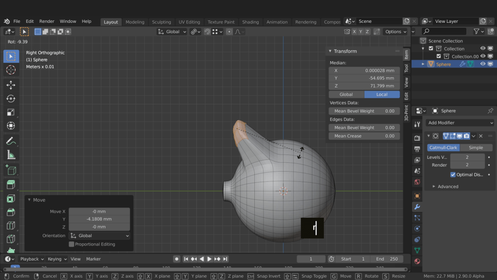
Press Numpad 3 for right side view. Press S, Y and scale the selection down. Press G, Y and drag forward. Press R and rotate these slightly.
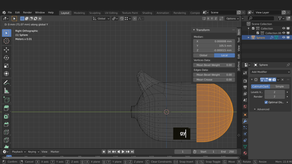
Press Z and switch to wireframe shading. Drag select all the faces from the centre back. Press G, Y and drag the selection back to extend the body.
Press Z and switch back to solid shading. Press Ctrl + Numpad 7 for bottom view. Press the home key to centre the mesh in the view. Press Alt + A and deselect everything. Press C and select four faces each side front and back. These can be used to extrude down the legs. Use the middle mouse button to deselect if you accidentally select faces by mistake.
With those selected press Numpad 1 for front view. Press E to extrude these out. Press the period key and switch to medium point. Press S, X and scale these along the X axis. Press the period key again and switch back to individual origins. Press G, Z and drag down to increase their length. Now flatten them on the bottom of the legs by pressing S, Z, input zero and enter.
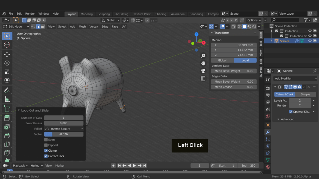
Press Ctrl + R and add an edge loop to each of the four legs. Then drag the edge loop down to flatten the bottom of the legs a little. Make sure no faces are overlapping after this is complete.
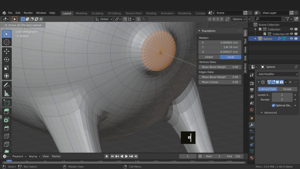
Press the period key and select medium point. Come to the back of the model. Press 1 for vertex selection. Select this centre vertex. Press Ctrl + Numpad + and increase that selection. Press 3 for face selection. Press E and extrude this out.
Press S and scale it down. Press E again and drag this out a little. Rotate and view this better. Now drag it back. We don’t want this so long. Press Numpad 3 for right side view. Press G and drag it up. Press I to inset and soften the corners.
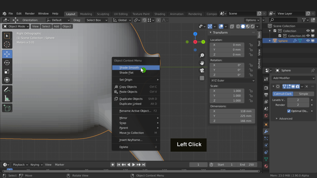
Press the Tab key and return to object mode. Right click and choose smooth shading from the menu. This will smooth the mesh. Smooth shading has highlighted some issues. These are sharp edges and bunching of the vertices.
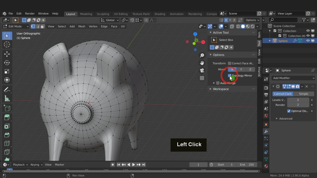
Press the Tab key and come back into edit mode. Press 1 for vertex selection and select this vertex here. Now in the tool tab, in options switch on X mirror. Also check on topology mirror. That way the vertices you move on one side of the origin will mirror across to the other side.
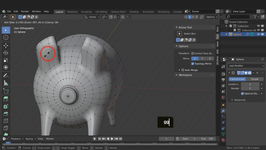
Press G, G for edge slide and slide the vertex. Repeat that for more vertices and reduce the sharpness and unusual shape of the ear.
Press Numpad 7 for top view. Press the home key to frame all. Press 2 for edge selection and select these 3 edges here. Double tap G and edge slide to reduce the size the opening.

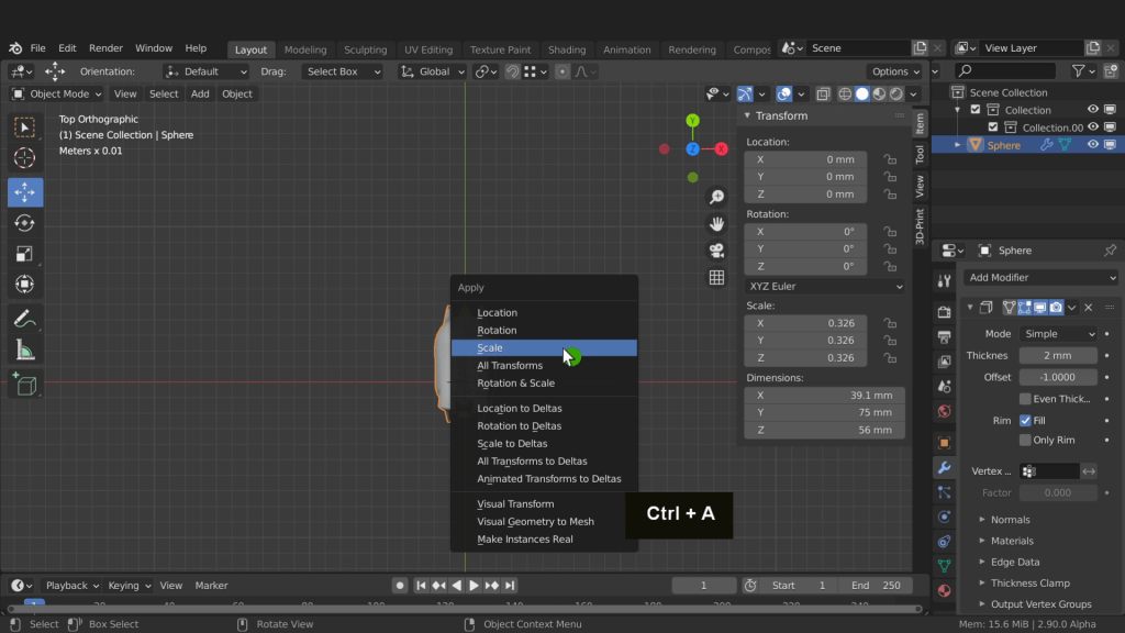
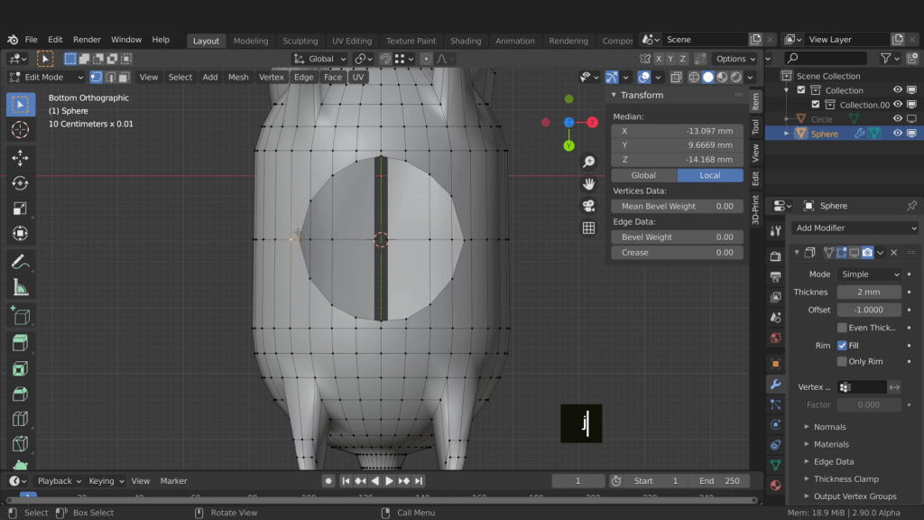
Now we can uncheck topology and switch off X mirror. Press 3 for face select. Select these faces each side. Press X and delete them. Press the tab key and return to object mode. On the modifiers tab click the X and remove the subdivision surface modifier. We can add a solidify and apply this first. That way we don’t need to worry about the order of the modifiers. Click add modifier and select the solidify. Set the thickness to 2 millimetres. Back on the item tab we need to check the dimensions. We need the longest part of the model to be 75 millimetres. Press S and scale this down until the Y dimension equals 75 millimetre. Press the Shift key to reduce the scale to smaller increments. Left click when that is 75. Press Ctrl + A and apply that non-uniform scale. That way the modifier is using the current scale of the object. This is important as the solidify modifier will use this scale when calculating the wall thickness.
Let’s hide the visibility of the solidify modifier. Press the Tab key and enter edit mode. We now need to create a hole in the base. That way you can withdraw your savings at any time. Press Ctrl + Numpad 7 for bottom view. Zoom in and select these two faces here. Now Press Shift + S and place the cursor to selected.

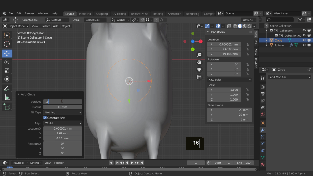
Press the Tab key and return to object mode. Press Shift + A and from mesh choose circle. In the circle properties reduce the vertices to 16. That will match the number of vertices on the bottom of the piggy bank.
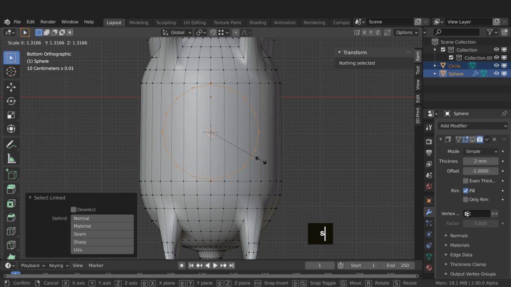
Press and hold Shift and select the pig. Now press the tab key and enter edit mode. Press 1 for vertex selection. Press Alt + A and deselect everything. Hover the mouse on the circle and press L. This will select all connected vertices. Press S and scale this to match the size we want the hole to be.
We can use the knife tool to roughly trace out the cut on the mesh. We can use the circle as reference. Press K for the knife tool. Begin underneath this centre vertex here. Left click and continue around and click where the circle either overlaps with vertices or edges. In situations where it only overlaps with the face click on the face and continue around. Just add vertices where necessary. We are currently adding vertices to the piggy bank mesh as that was the active object. The active object will be the one the knife tool will cut. To finish click back on the first point and press enter to exit the knife tool.

With all these selected let’s tab to object mode. In the Outliner hide the visibility of the circle.

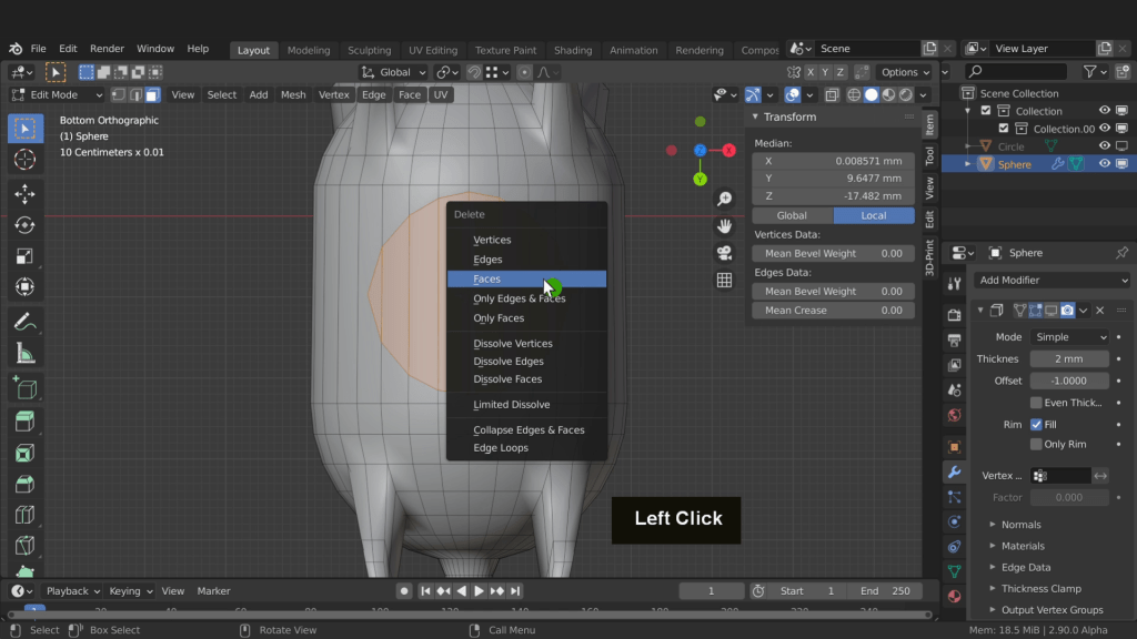
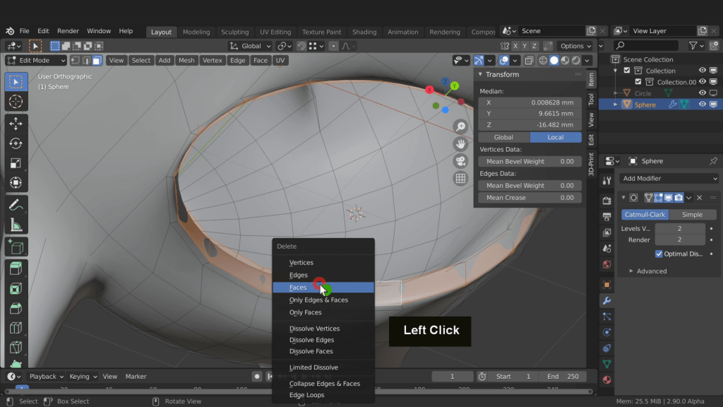
Select the piggy bank again and tab into edit mode. Press 3 for face select. Press X and delete the selected faces.
Switch back to vertex selection. We now need to form quads or four-sided polygons on the model. First press Ctrl + R and add an edge loop to this side. Left-click and right-click. Now add an edge loop on the opposite side. Select these two vertices, then press j to join them and connect up that edge all the way around. Repeat that on the opposite side also.
Now Alt select this edge loop. Right click and from loop tools choose circle.
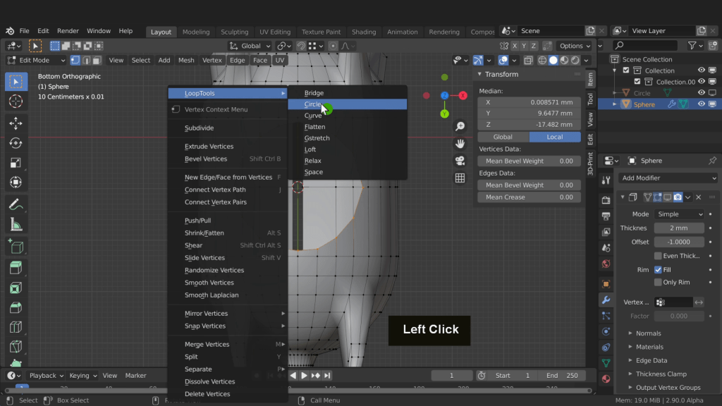
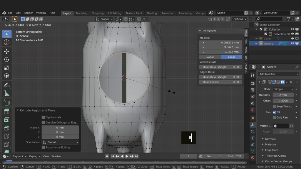
This will form a circle shape from the selection and make it easier to work. Press R to rotate and align to the edges. Press E to extrude and right click. Now press S and scale this in a little. That will just help hold this edge.
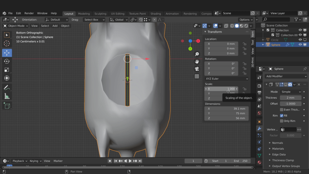
Next press the Tab key and return to object mode. Make sure your scale is applied. That is the scale is 1 in the X, Y, and Z. This is important as we will apply the solidify modifier now and the new wall thickness will be based on the scale value.
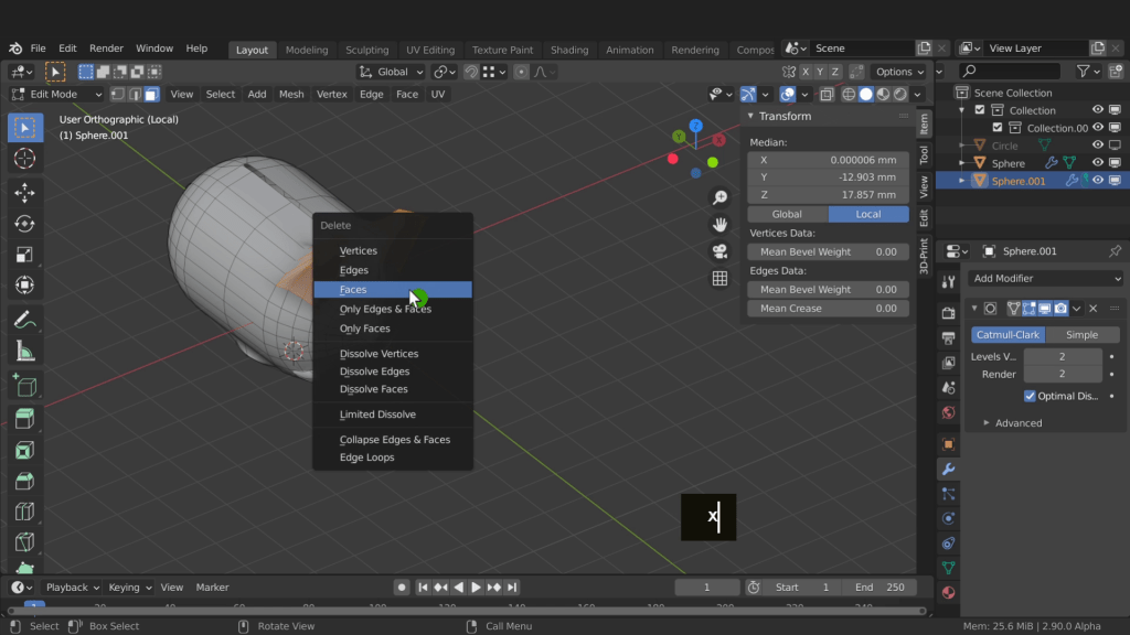
Over in the modifiers tab make the solidify modifier visible again. Then hovering the cursor over it press Ctrl + A and apply it. Back in the scene press Ctrl + 2. This will add a subdivision surface modifier with levels of 2 onto the mesh. Press the Tab key and enter edit mode. We need to remove any areas of the mesh that may have overlapping faces. The bottom of the legs for example and the areas within the ears will have faces very close together. These will cause errors on the 3d print add-on so now is a good time to fix them. Zoom into the top section. This object is connected inside to outside by this edge loop here. Press 3 and select this edge loop. Press delete and select faces.

We also need to remove the connected faces underneath. Rotate around and zoom in. Press Alt and select this edge loop. Press X and select faces.
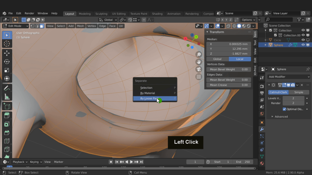
Press A then press P and choose by loose parts. That will separate the mesh into two shells.
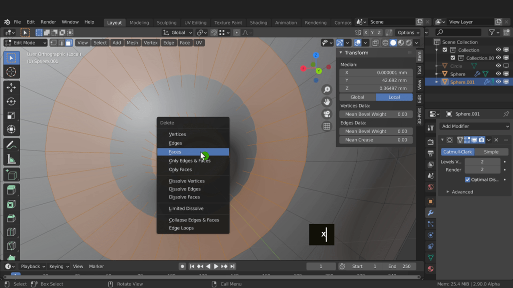
Press the Tab key and return to object mode. Select the inner object and press the forward slash key to enter local view and isolate it. Press the Tab key and enter edit mode. Press Numpad 1 for front view. Press Z and choose wireframe shading. Drag select all the bottom faces and press Ctrl + Numpad + to increase the selection. This increases the selection to include the entire leg section.

Press Z and switch back to solid shading. Rotate around and press X and remove faces. Select the faces around the ear both sides. Press C for circle select and select the remaining faces. Press X and remove faces.
Press C and select all the faces on the front of the nose. Press Ctrl + Numpad + to increase the selection. Press X and remove faces.

Rotate around to the back and zoom in. Press C again and select these faces here. Make sure to select all of these. They are a little messy and overlapping because of the solidify modifier. Press delete and remove those faces.
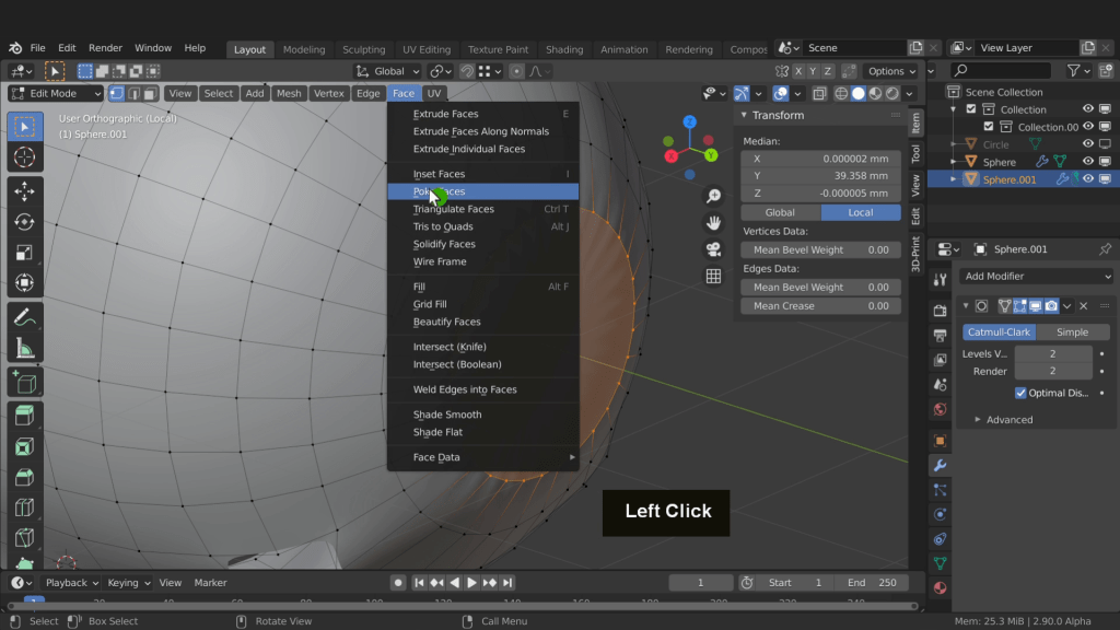
Press 1 for vertex selection. I have missed some vertices here. I can select these and delete them. Select this entire ring and press F. From the face menu choose poke face to finish that off.
Rotate around to the front legs. Select this entire ring and from the face menu choose grid fill. That doesn’t give me the results i want. So press Ctrl + Z to undo that. Instead press F to create a new face here. We will need to create quads. So select the opposite vertices and press j to join them.

The join command is great and will connect vertices through other edges if necessary. Repeat that on the opposite side and create a face. Use the join command to connect them up and create the quads. Repeat that for the back legs and create quads. Repeat that for the opposite side also. Rotate to the top and fill in both holes where the ears once were. Also remove any extra vertices we may have neglected to delete. Return to the front of the mesh where the nose used to be. Alt select this edge loop. Press F and create a new face. From the mesh menu poke face.

With that done press the forward slash key and return to global view. Press the Tab key and return to object mode. We can now join these object back together. Press and hold Shift and select the outer mesh. Press Ctrl + J and join these back together. Press the tab key and enter edit mode. Alt select both the top and bottom edge loops. Right click and from the loop tools menu choose bridge.

We also need to repeat that underneath. Rotate around and select the top and bottom edge loops. Now right click and from loop tools choose bridge.

To finish off this opening press 2 for edge selection. This is where an inset can be used to seal the bottom of the piggy bank. Press Ctrl + R and add an edge loop. Push and move that towards the top. Add another and add one to the bottom. With this still selected press Shift + D and duplicate it. Right click to exit move. Press P and choose by selection.

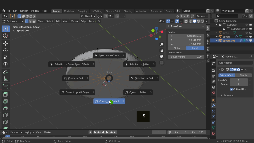
Now press the Tab key and return to object mode. Select the circle and tab into edit mode. Press A, F and now press I to inset. Bring that in a little. In the face menu choose poke faces. Press A, E input 3 and enter. Press the forward slash key to isolate it. Press Ctrl + R and add an edge loop. Push that up towards the top add a second and push towards the bottom and just tighten up those areas a little. Alt select and shift select the top 3 edge loops. Press S and scale this down a little. This will be a wedge piece that can be pushed into the opening. This piece can be printed separately and tested until you get one that fits. Let’s select the bottom vertex. Press Shift + S and choose cursor to selected.
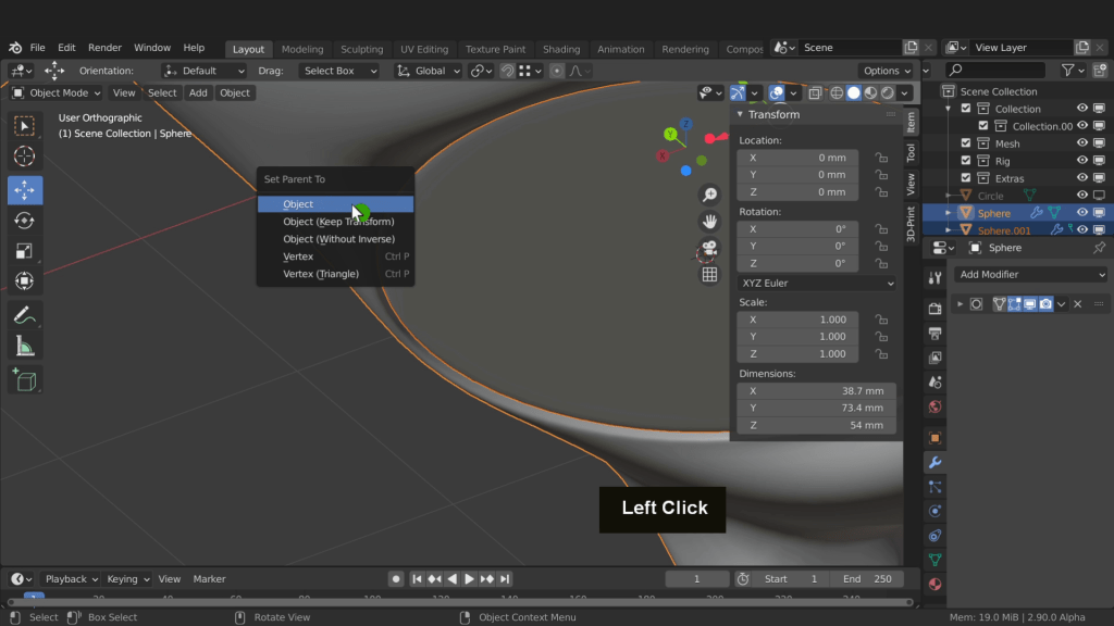
Press the Tab key and return to object mode. Right click and from set origin choose origin to 3D cursor. Right click and choose shade smooth. Press the forward slash key and return to global. Let’s set the origin on the base of the piggy bank first then position both objects on the grid. We do however want to maintain the position of the inset in relation to the piggy bank so we can parent the inset to the piggy bank first. With the inset selected Press Shift and select the piggy bank. Press Ctrl + P and choose object.
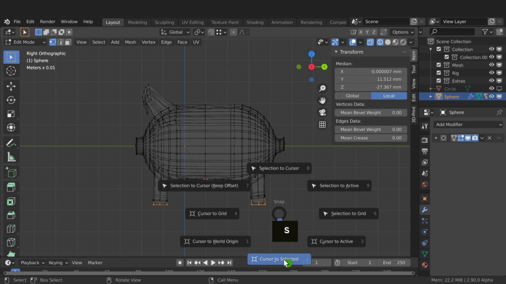
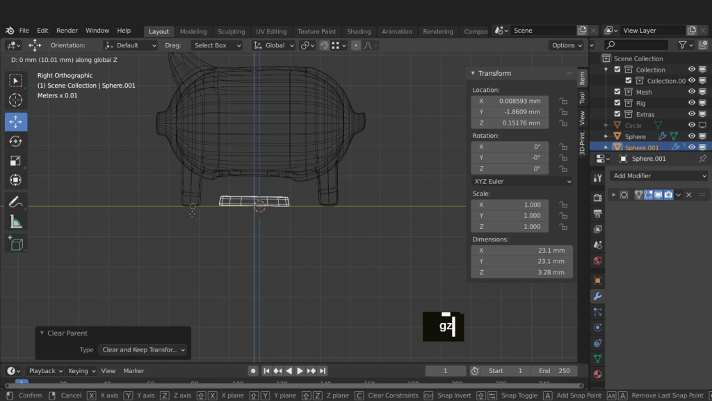
That will parent the inset to the piggy bank. Press Numpad 3 for side view. Press the home key to frame all. Select the piggy bank now. We can set the origin of the piggy bank to be at the lowest point on the model. Press the Tab key and enter edit mode. Press Z and switch to wire frame shading. First we need to bring the legs underneath the body, as they do look a little bit split out. Drag select the front set, then press G, Y and drag these back. Drag select the bottom then drag these to better line up. Repeat that for the back legs and drag them forward and line them up as best you can. Drag select the bottom row of vertices across all legs. Press Shift + S and choose cursor to selected.
With that done tab back to object mode. Right click and from the set origin menu choose set origin to 3d cursor. Press Shift + S and choose cursor to world origin. Press Shift + S again and choose selection to cursor. Select the inset now and press Alt + P and choose clear and keep transformations. That will remove the parent child relationship and keep the inset in its current location. Press G, Z, press and hold Ctrl and snap to the bottom most vertex. This is in line with the grid floor. I’m going to test print these objects together. If the inset fails to fit the first time i can experiment and maybe change the material or reduce the model in size. You can alternatively add treads to both models and make this a screw-in bottom. For this example I’m going to leave it as a push-in, but feel free to experiment.
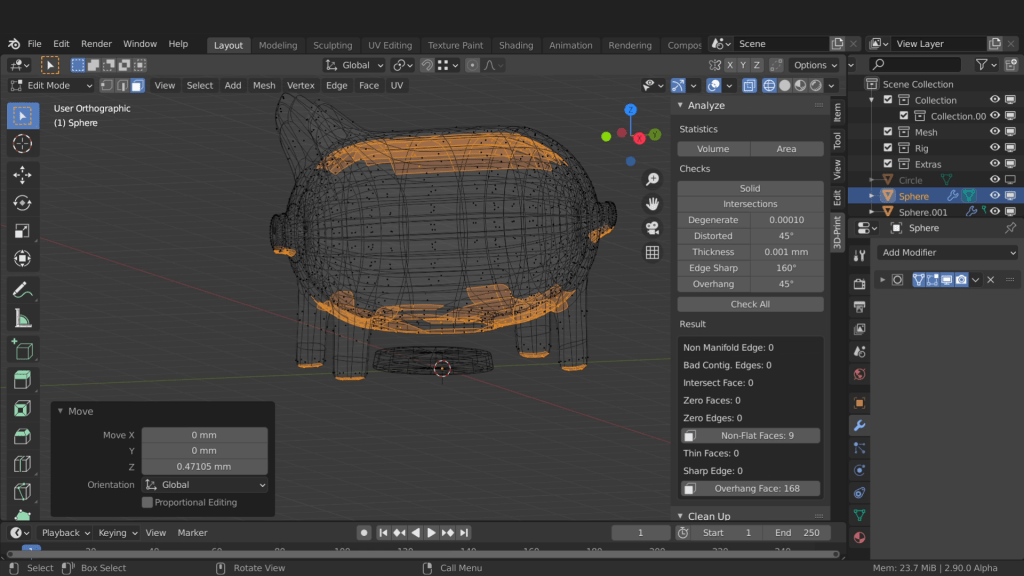
Press the Tab key and enter edit mode. In the 3d print add-on click check all. The first issue listed are intersecting faces. Click this and take a look on the model.
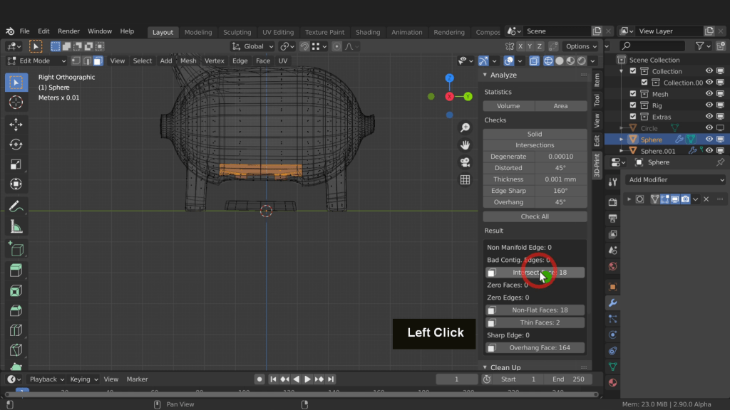
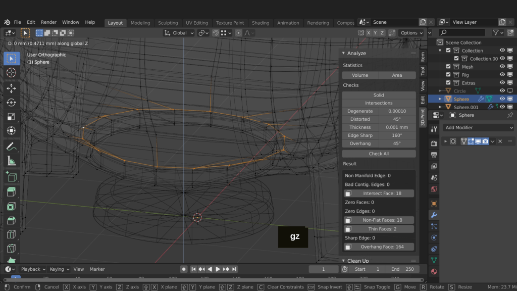
Zoom in and rotate around. Press Z and switch to solid shading. Select this edge loop here. Press Ctrl + Numpad + twice and increase the selection. Press Z and switch back to wireframe shading. Press G, Z and drag this down to help straighten up this area. Rotate around a little. Drag this down a little further and left click. Press 1 for vertex selection. Alt select this edge loop here. Press G, Z and drag this up to help flatten the top faces.
Back on the add click check all. That has fixes those issues. Click non-flat faces and take a look. On the modifier I will enable this option here. This will make it easier to identify issues.
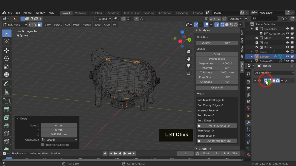
Now take a look at these faces on the model. I don’t believe these faces will be an issue. None are overlapping and they shouldn’t be a cause for concern.
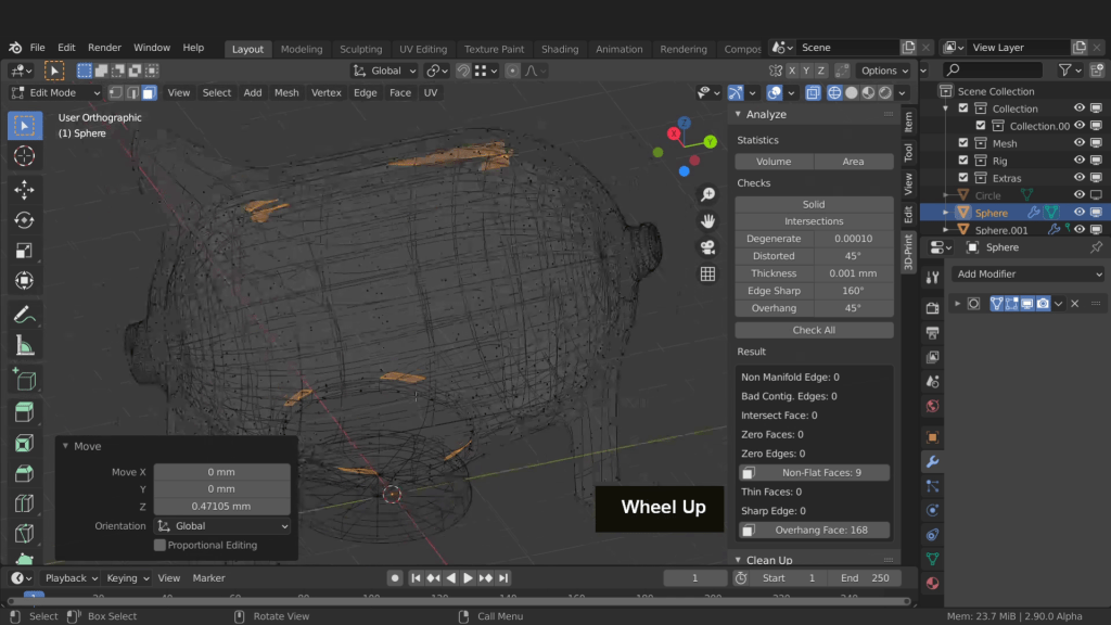
The next result on the add-on are overhanging faces. These are obvious issues on the belly for example. These will be hanging in mid air. Also the nose and the tail are not supported and extending out at 90 degrees. We do have a couple of options. The first is to add support material in blender. That involves creating thin mesh objects and inserting them beneath the overhanging areas. Another option is to use the support function in the slicer software. I find this option works well as it only adds the minimum amount needed. It is also a great way to discover how you might approach the creation of your own supports in future. We can take a look at that when we import this model into the slicer. The inner faces on the top are also overhanging and may be an issue. We can increase the detail of the print and this may help. Also slowing the print speed down may reduce the risk of failure. Making sure the material cools and stays in position.
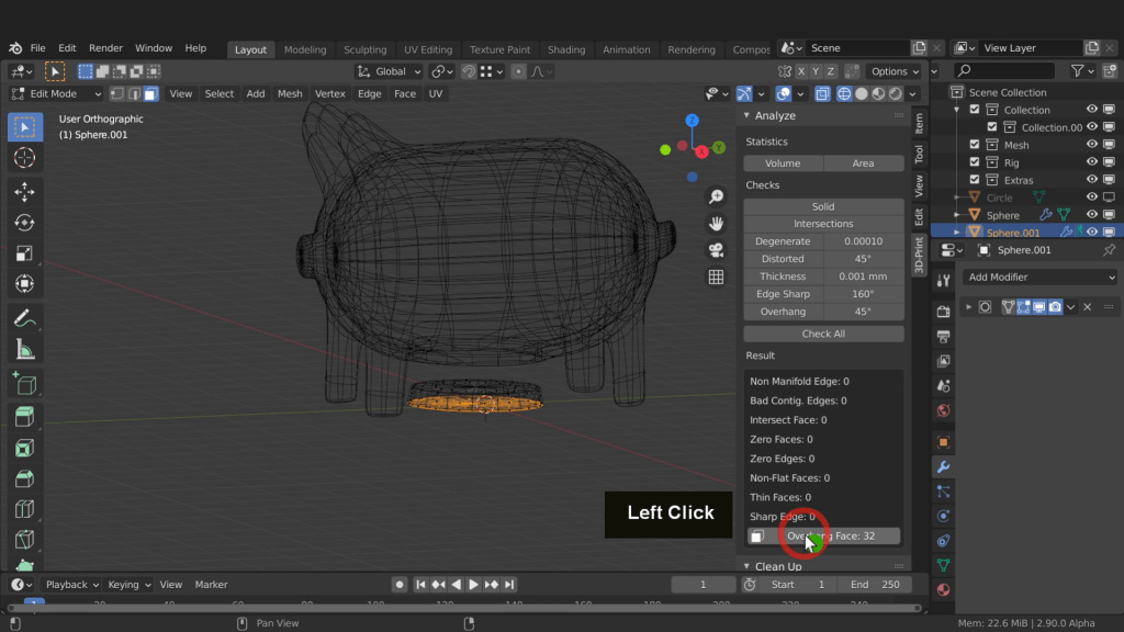
Let’s press the Tab key and return to object mode. Select the cap object now and tab into edit mode. We can click check all for this model. The only result showing are overhanging faces and these are on the build plate so they will not be an issue.
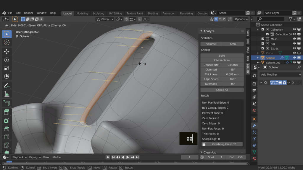
Press the Tab key and return to object mode. I did notice the opening is a little narrow. Press 3 and rotate around. Press Z and switch to solid shading. Select the internal faces along this side up top. Enable this X mirror option. Back in the scene double tap G and drag this out a little and left click.
Press the Tab key and return to object mode. Shift select the inset. We can now increase the size of these objects as they are a little small. Press S 1.2 and enter. Press Ctrl + A and apply all transformations.

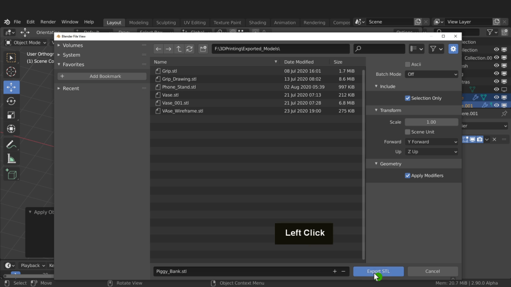
With both these objects selected press F4 and from export choose the stl file format.

Navigate to a location to save this file. In the name field i can call this piggy bank. Up top check on selection only. That way only what you have selected will be exported. Now down on the bottom click export stl.
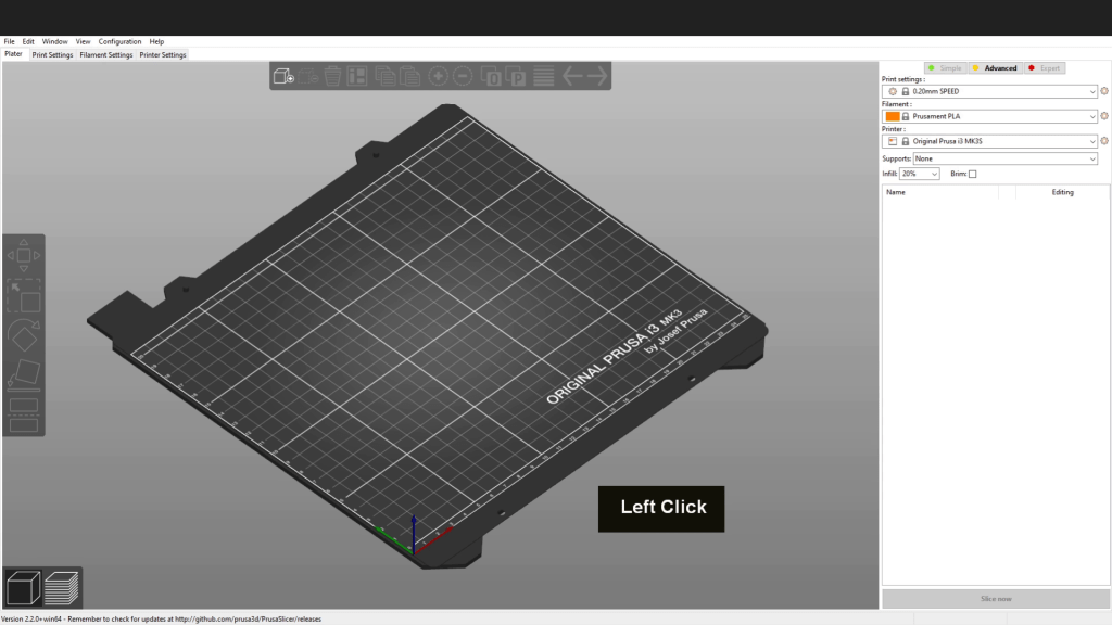
We can now open up the Prusa slicer software.
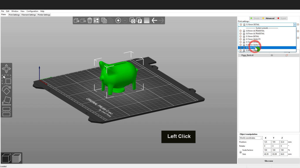
Come to file, down to import and across and choose stl. Navigate to where you have saved the stl file. Select it and click open. This is a small model and a good size to begin testing. This can be scaled up once the model prints as expected. In the settings area set this to detail. That will help the inner faces on the top of the model and the material overhang will be reduced by the finer detail. However to speed this print up i can set this to the speed setting.
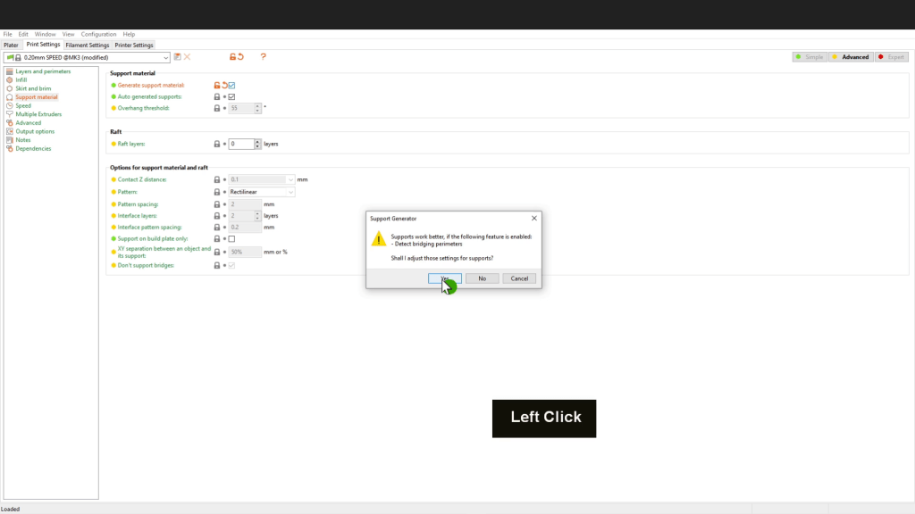
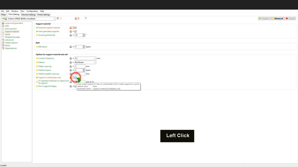
Now come up to the printer settings up top here. Down here in support material i can put a check mark in generate support material. You will need to click yes to update that change.
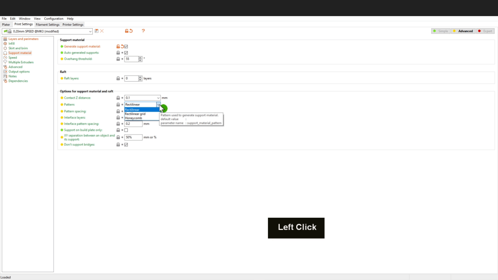
In the pattern menu you can change the type to one of these. This refers to the type of support structure that will be built. I can leave this at the default.
Also check on support on the build plate only. That way no support material should be placed inside the model. They are the only changes we need to make.
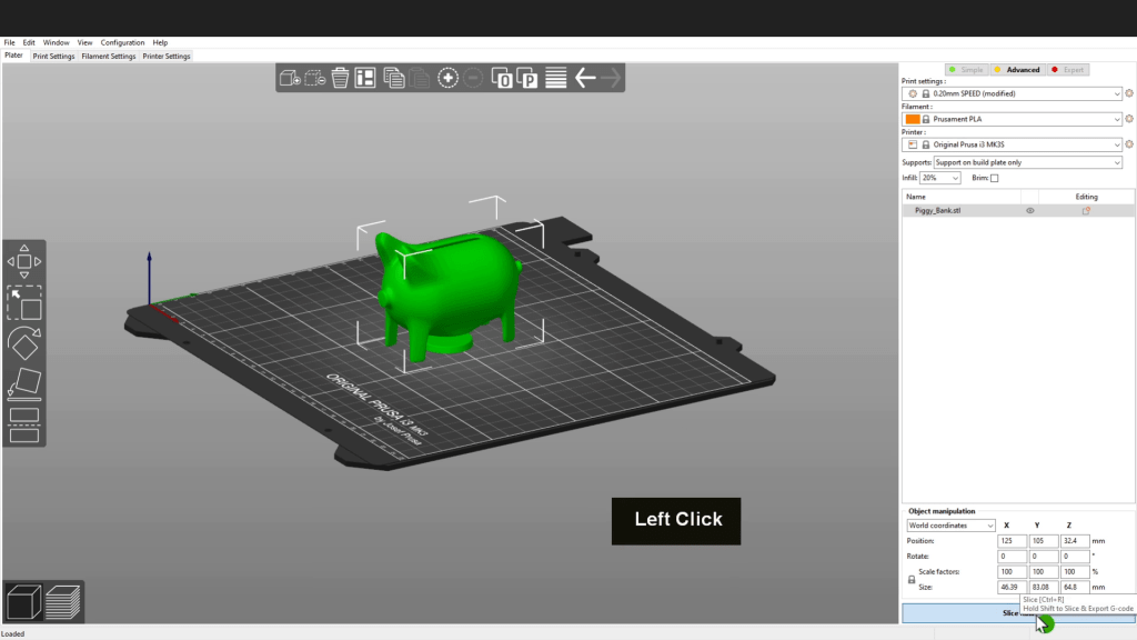
Now come back to the platter tab. Down the bottom i can click slice now.
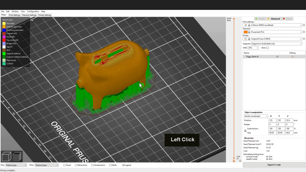
When that completes we can see the green material represents the support material. We can also see there is a little support material inside the model. This will be easily removed after the print has completed. The support material is very light and easy remove. There is most lightly a gap there and the support material was created to fill that gap. The file is now ready to export.
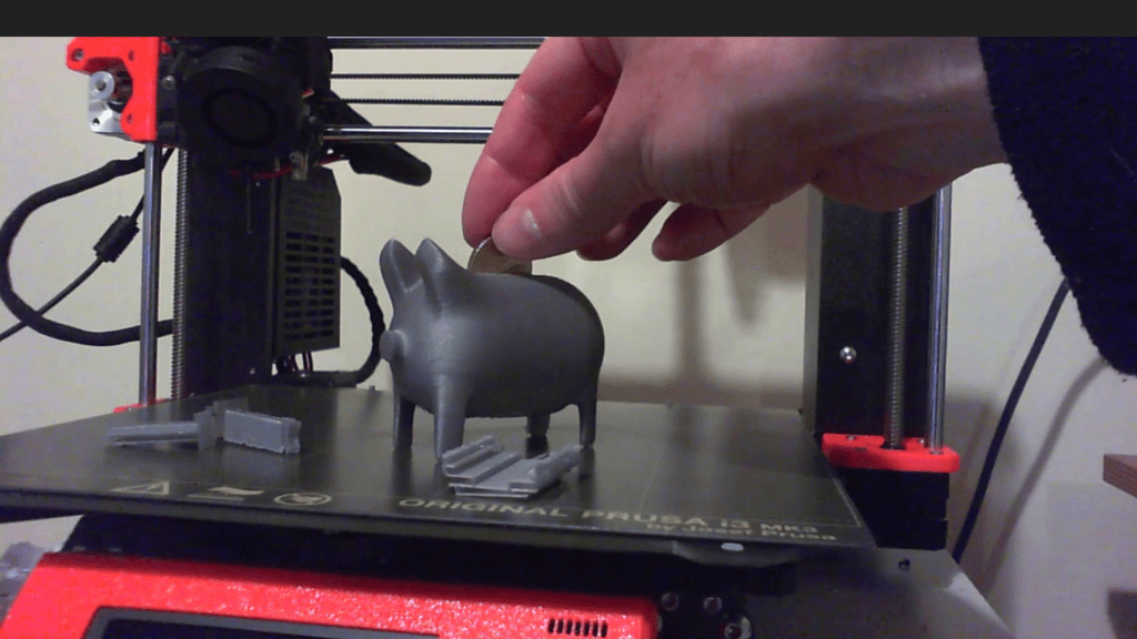
I can speed up the next part of this process and we can take a look at this printing. The model printed successfully. The support structure released very easily from the model and while you do need to be careful separating it the support only attach very lightly to the surface of the model when models have very delicate pieces extra care should be given as small pieces can give away when removing the supports. The internal structure also came away really easily with no issues. The inset for the base fits in perfectly but tends to pop out when coins are added. Adding a threaded opening is probably necessary here when the model is printed full size. I’d recommend testing the threads on small object first before incorporating them into the full model. Time to start saving in the new piggy bank and that’s where i leave it.
Start designing, modelling & printing your own unique models
If you’d like to learn more find details of my 3D printing course here.
