

MeasureIt is a measurement display add-on for Blender that lets you add dimensions to your models. The tools displays accurate measurements for your design projects in the viewport. These measurements can be rendered using the scene camera and combined with the rendered model.
In the following post I’m going to work through the MeasureIt add-on and complete these layouts with dimensions as you see here. If you’d like to follow along follow the link to the asset page on my website where you can download this blend file. If you prefer to watch video tutorials. Click here to view the video tutorial version. Get to the next level in 3D creation with this very detailed course on Udemy. Follow the link for a detailed description of my courses on Udemy.
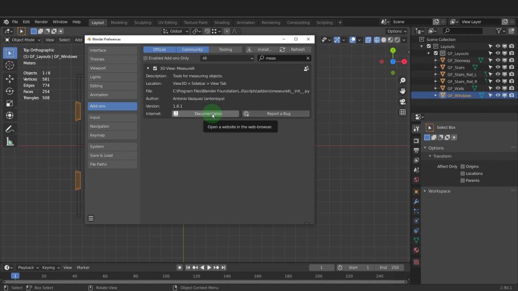
We can begin by enabling the add-on first. Press F4 and come to preferences. Open up the add-ons tab. The MeasureIt add-on is listed close to the top but just start typing MeasureIt and it will appear. Left click and add a check mark in the box and enable the add-on. Expand the drop down menu. The location of the MeasureIt will be on the side bar and in the view tab. Click documentation for detailed information on the add-on. Clicking this will open a web browser into the Blender docs.
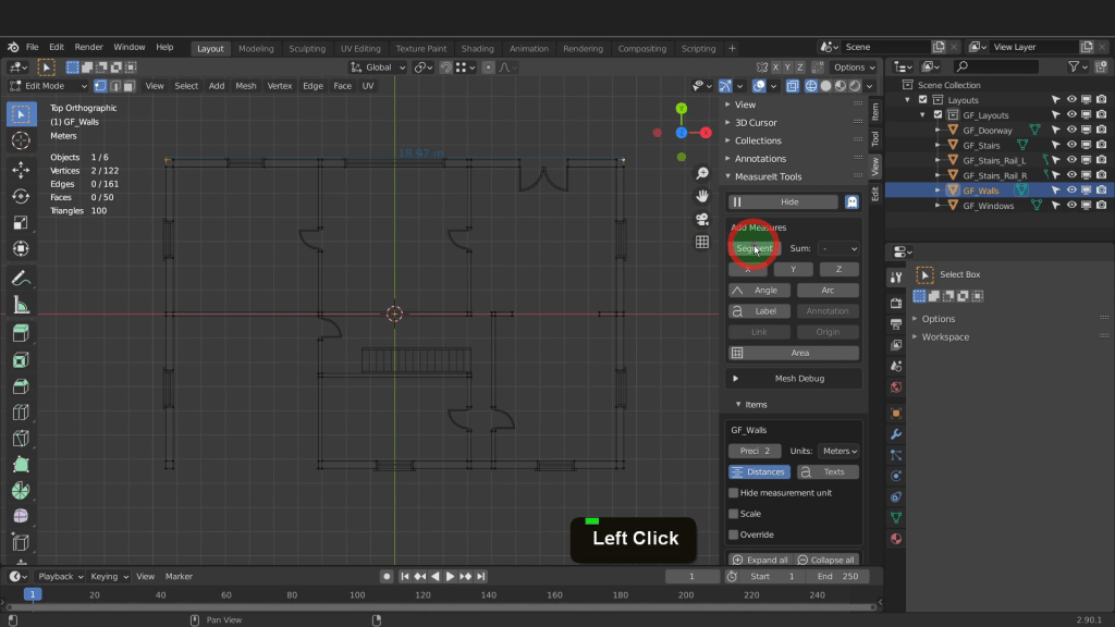
With this enabled X down preferences. From the 3D view press N to open the sidebar. Open the view menu for the MeasureIt add-on. Minimize any open tabs and make some room. Here we have the MeasureIt tools. Expand the add-on to reveal the settings. By default MeasureIt begins with all MeasureIt dimensions in the file hidden. Click the show button and make them visible.

This first setting is segment. This will get the distance between two points. To add a dimensions to an object you need to be in edit mode. Lets select this outline here and press the tab key to enter edit mode. Change the snap type to vertex up top here. Select an end vertex, press and hold Shift and select one on the opposite end. To get the distance between these two vertices click segment.
This creates a dimension based on the configuration settings on the add-on. We can make some changes and create a style for how we’d like these dimensions to look. First click in the colour and change this to a dark colour. This separation setting determines the distance the dimension will be offset from the vertices. Increase this to 0.3. In the alignment drop down choose a type here. I can change this to centre and have the dimension sit centre on the dimension line. In the arrow type drop down change the type of dimension line end. Here I can use triangle for both ends. Adjust the size setting if necessary. 15 woks fine. The final setting is font size. I find 20 works well for dimensions.
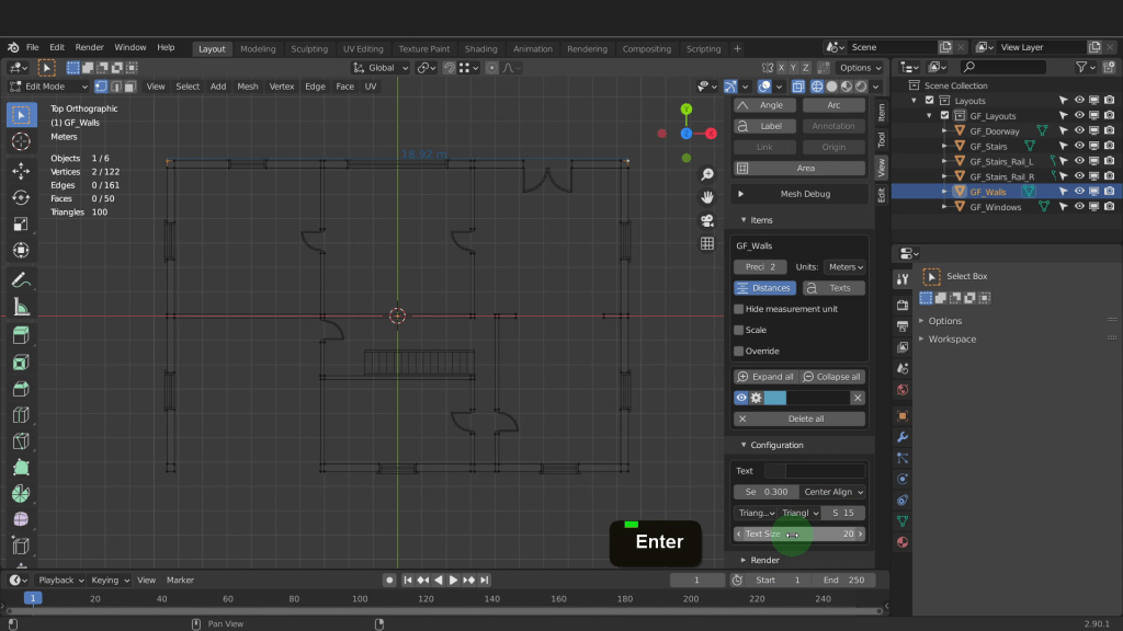
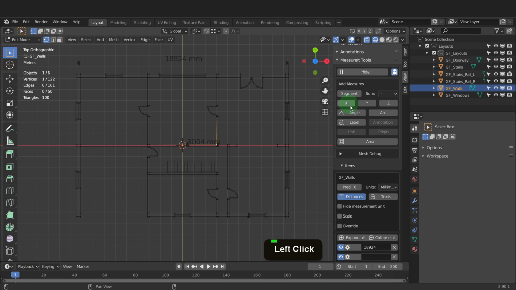
Lets come back and X off that first dimension we created. These have the default dimension configuration settings. With the two vertices selected click segment and add a new dimension based on these new settings. In the new dimension click into the name field and give this a descriptive name. I usually input the actually dimension value. 18924 will do here. Click the gear icon to reveal the dimension style settings. These include the configuration settings. I usually uncheck automatic and this reveals the X, Y and Z fields. Because this dimension is on the Y axis we can click into the X and zero it out. Tab into the Y and input 1. That way when we adjusting the distance setting moves the dimension and keeps it centre on the y axis. Increase the Y value and offset the dimension from the dimension line.

On the add-on you can also change how the units are displayed. Click the drop down and choose one from here. I can select millimetre.
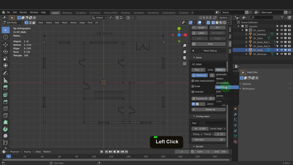
Also adjust the precision to suit. In this case zero will work fine. The next tool on the add-on are X, Y, Y. This will give you the dimension from one vertex to the objects origin. The origin of this object is at 0,0,0. Select a vertex on this outline. Now click the X. This will create a dimension from that vertex to the origin along the X axis. Use Y and Z for those distances also. Name the dimension in the name field. Expand the settings and make the necessary adjustments. I can un-check automatic position and zero out X and input 1 for the Y. Now use the distance value to update the offset.
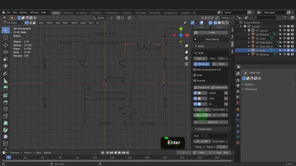
The next tool is the angle tool and requires three selected vertices. The second is the angle vertex of the selection. So for example I can select three vertices around this 90 degree corner here. Now on the add-on click angle. Lets name this dimension. Expand the settings and adjust the position of the text. -47 for the X and 37 for the Y.
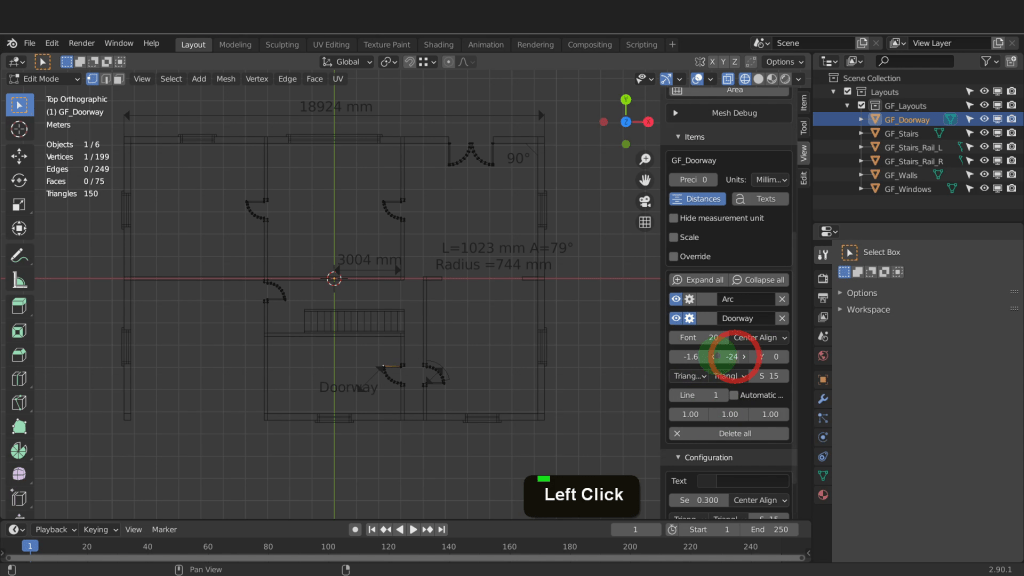
For the Arc tool lets tab back to object mode and select the door outlines. Now tab back to edit mode. Similar to the angle dimension the arc dimension also needs three vertices. We can select a start a center and an end point. Now click arc. The settings for this dimension are similar to the previous ones with some additional options to display the radius length an angle. Click into the text field and here I can type Radius = and press enter. This will get updated on the dimension. Offset this on the Y axis now and move it up.

The next tool on the add-on is the label. Select one vertex to be able to add one. Click label to add one into the scene. In the name field input text. I can input doorway and press enter. Expand the settings to make adjustments. First I can un-check automatic position. I usually input 1 for the X, Y and Z values. This allows you position the label more easily with the distance value and the X, Y positions. The rest of the settings are what we have seen before.
The next tool is the annotation tool. Tab back to object mode for this tool to become available. Lets first press Shift + S and place the cursor back to world origin. Click the annotation button and this will get added at the position of the 3D cursor. This is just an origin point but in the Outliner it is listed here. Press F2 and rename it. I can call this Kitchen and press enter. If you press G in the scene you can move it but best leave it where you add it and use the settings to position it. I can right click to cancel move. On the add-on I can click into the text field and input kitchen and press enter. Now expand the settings. Here you have the basic settings to position on the X and Y axis. Change the font size or change the alignment setting.

The link option tool lets you get the distance between two different objects. Lets get the distance between the hand rail and the end of the stairs. We could just get the length of the hand rail but lets use the link tool as an example. First select the hand rail and tab into edit mode. Select this end vertex here.
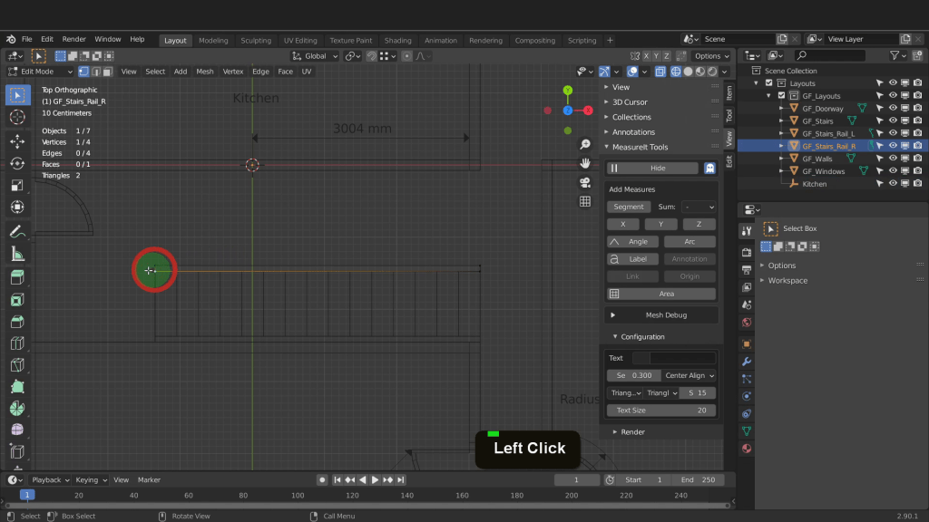
Tab back to object mode now. Select the first step and tab in here. Select the vertex on the opposite side.

Now we can tab back to object mode. The link tool will calculate the distance between the two selected vertices in each object. We need both objects selected so press and hold Shift and select the hand rail. On the add-on click link. Now we can come down to the properties. I can name this 4500 and press enter. Now expand the settings. Increase the value to 10 on the Y axis.

The next tool is origin. Similar to the object origin we previous saw you can add this in object mode. If you select a vertex in edit mode you can get the distance from the vertex to that origin. Next is the area measurement. To create an area you need to have a face selected. Select the wall outline and tab into edit mode. First select four vertices of a room within the layout. Press the F key to create a face. Now on the add-on click area. I can name this Floor area in the name field. Here you have two color choices. The first will change the color of the text. Update the color there. The second will change the color of the fill.

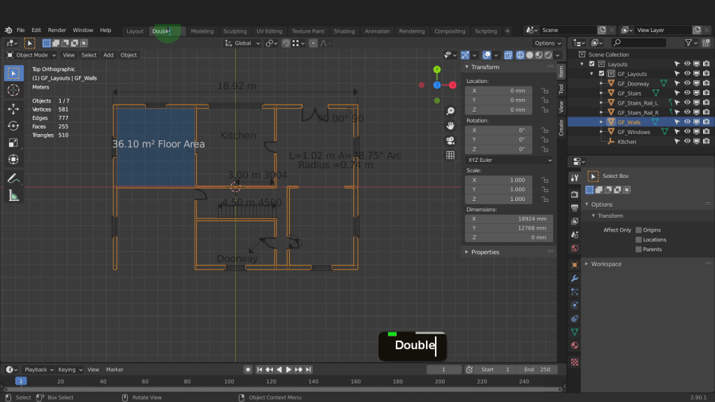
To display the area in metres, change the units to metres from the units drop down here. You can also increase the precision to 2 places. Enable text here. This will display the text within the text field. This updates to all the dimensions but each can be switched on or off from within their respective settings. So for example with both distances and text enabled I can expand the 18924 and now switch off text from here. Alternatively change the text that gets displayed and leave text enabled. Lots of options to customise the dimensions the way you need them. The you have the mesh debug where you will get information for the selected object such as the number of vertices, edges and faces. The location and normal information.

I can minimise this. Lets look at adding a camera and rendering the layout and dimensions. We will setup and use an orthographic camera to capture the layouts and dimensions. We will be using Freestyle to render the outline. Freestyle is an internal render engine that draws hard lines on mesh objects using a line style. Freestyle requires the mesh to have a face and it will render only the outline of that mesh. First we can first make a double viewport so its easier see now to control the camera. We can do that up here in the layout tab. Right click and choose duplicate. I can double click this and rename to double and press enter.
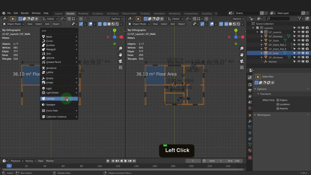
To make a double viewport over here on the top right I can hover the cursor until I get a plus icon, then left click and drag to split the viewport.

To make more room in each viewport press T and N to close up both the tool and sidebars. Do this for both view ports. I can press Shift + A and from the add menu choose a camera.
I’ll press N to open back up the sidebar here so we can modify the rotation of this camera. We want this camera pointing directly down and capturing the entire outline. First we can zero out the cameras rotation transforms. I can input zero for the X, Y and Z. Zoom in and take a look at the camera. This leaves it pointing directly downwards. The apex or tip of the camera is where everything is viewed from.Right now the tip is at the same position as the outline so the camera will be impaired by the plane.
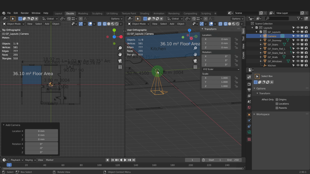
When you work with cameras in Blender the active camera will be the one used by the render engine. Because this is the only camera in the scene it will automatically becomes the active camera. You can tell an active camera by the fill in the triangle over the top. We can enter camera view in a number of ways. This button here will bring you into a camera view. Pressing Ctrl + zero will also bring you into the camera view and make that camera active.
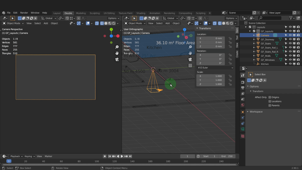
This is the view from the camera now. The frame is an indicator of camera view. We can leave this viewport as the camera view as we continue to setup the camera position within this viewport on this side. Getting to grips with the camera in Blender is fundamental if you plan on rendering images or animations. I can left click in the Z location and drag to move the camera on the Z axis. As I do the mesh becomes visible through the camera view. To finalize the camera position we first need to change the camera from a perspective to an orthographic.
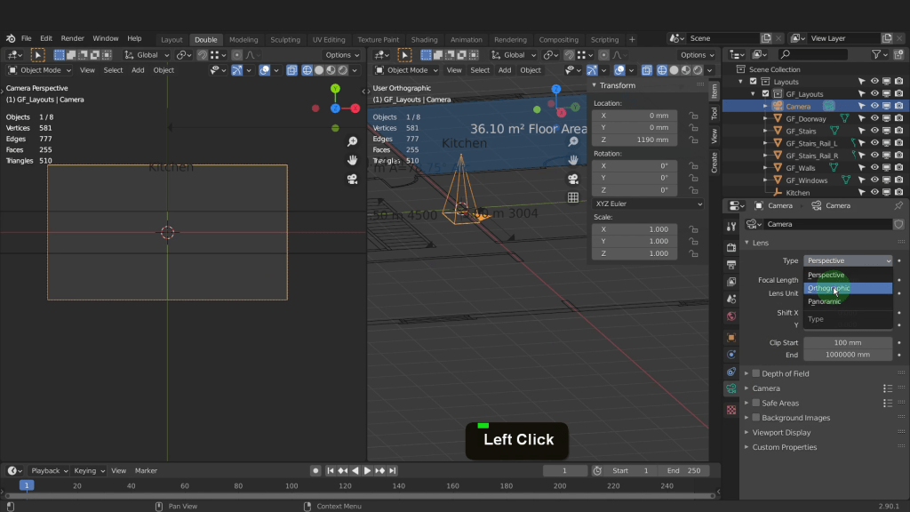
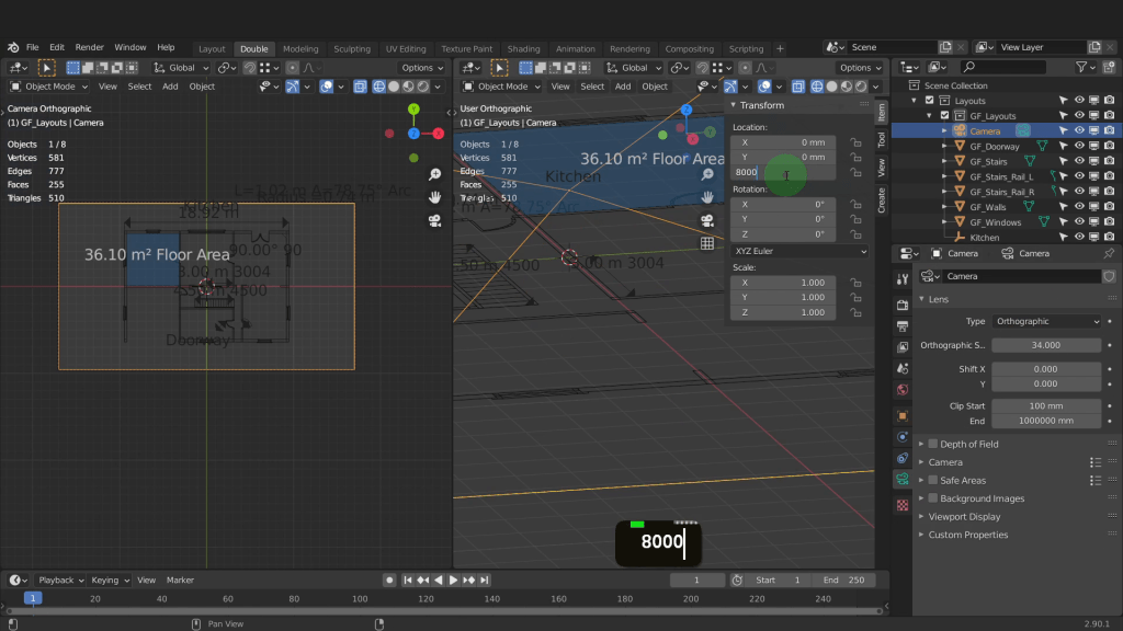
We can do that over here in the camera properties. From the camera type drop down we can set the type to orthographic. We can now bring the plane into view by increasing the orthographic scale. 34 works well for this layout. I can move this camera up so enter 8 metres in the Z axis and move it right up.
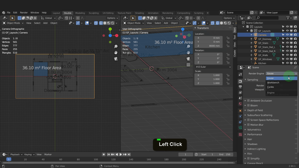
Lets render the view from the camera. First we can come over to the render properties tab. The default render engine is the real-time engine Eevee as its the one selected from the drop down here.
To render the camera view we can come up to the render menu up top here. From here we can choose render image.
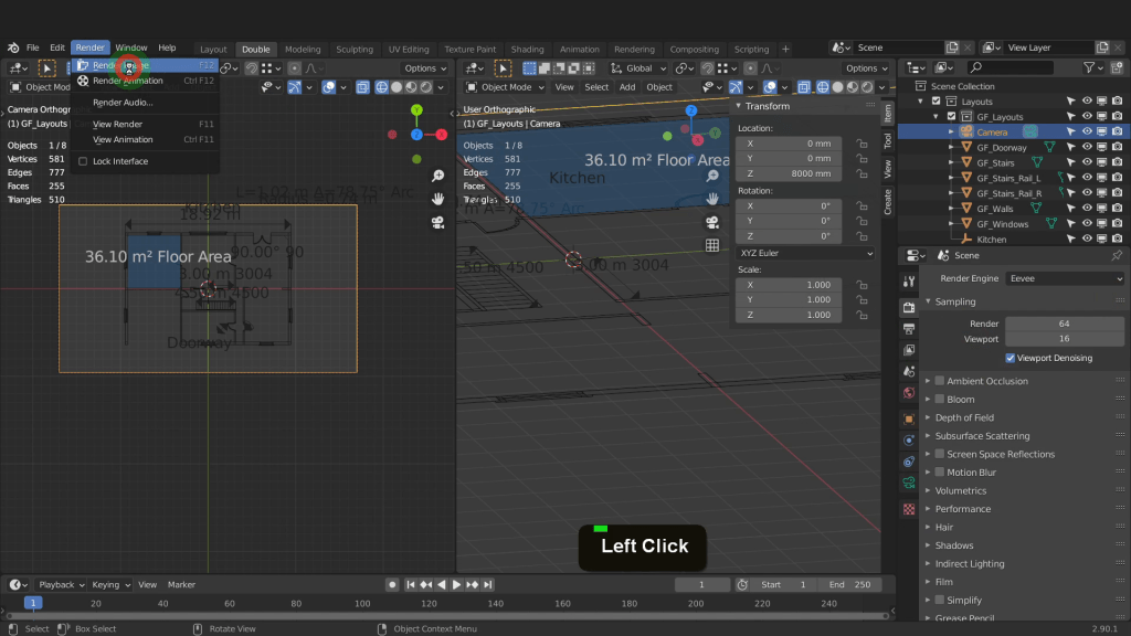
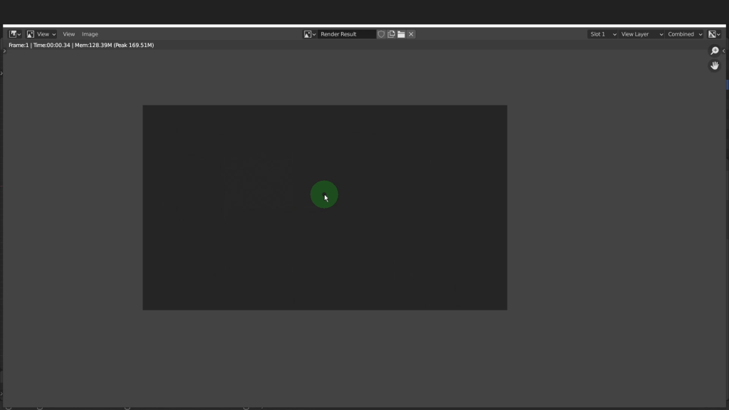
A separate image editor opens and renders the image. Right now the image shows a dark representation of the plane and the surrounding environment.
I’ll first X this image editor down. Lets come back to the render properties tab. We can scroll down to the bottom. Put a check mark in here to enable Freestyle. I can also click the drop down. Here there are additional settings to change the line thickness mode and line thickness. I will leave the defaults as they are.

Lets come to the layer properties tab where there are more Freestyle settings available once freestyle is enabled. Here we have the freestyle line set and these settings are what the freestyle render will be based on. Below this are the Freestyle line style settings. Here you can modify the line style from the stoke to color thickness to texture. In thickness I can reduce the line thickness to 2.

This will narrow the line rendered and this can be adjusted later you need to increase or decrease the line width. We don’t need to change any other settings at the moment. Just be aware you have full control over how the Freestyle line render will display from these settings here. The next thing we need to do is make sure there is a material on the outline. Lets come to the material tab. Here we have a material I added earlier on this object called outline.
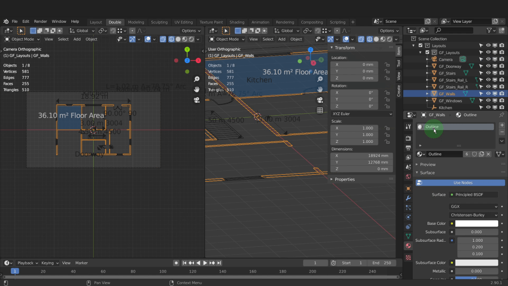
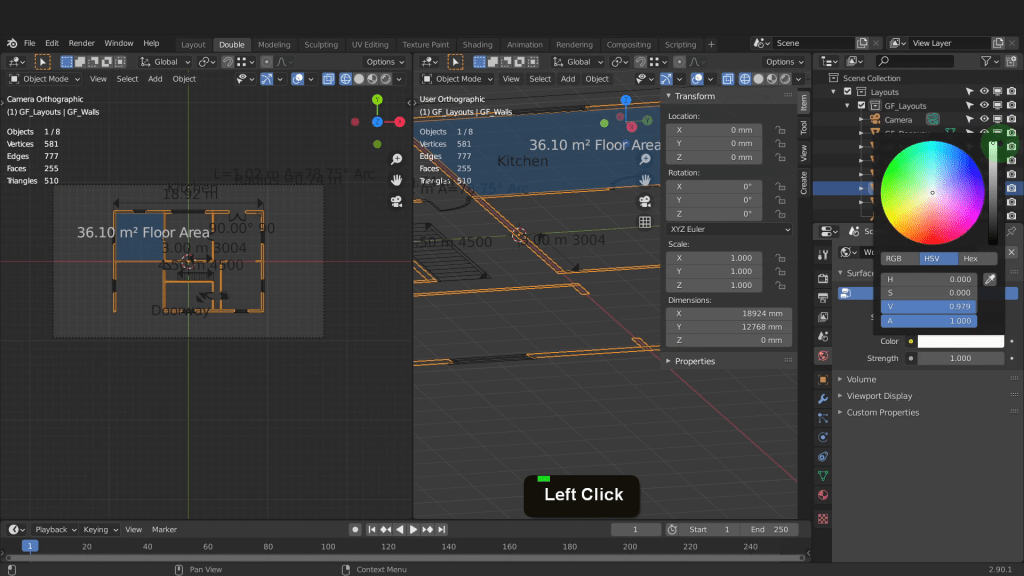
Next we can come to the world tab. In the world tab we can click into the background color and increase this to fully white. This will brighten the scene and match the outline color. The scene color has a major influence over objects during render.
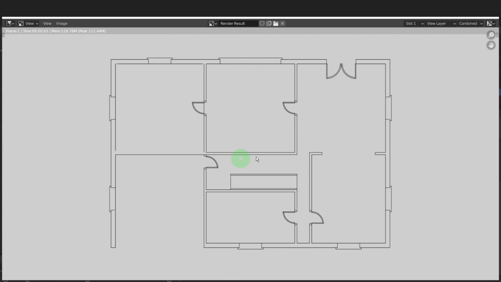
Lets now press F12 and give this a render. Give this a moment to render. The freestyle render is adding the black outline to the plane. This will be the result we expect using freestyle. Only the outline of the mesh will render using the default settings. You can specify edges to be included in the freestyle render if needed. One thing you’ll notice is dimensions were included in the render. The MeasureIt dimensions are rendered separately then must be combined in the compositor. Lets look at that process now.
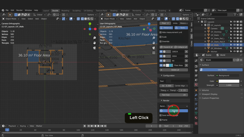
Lets X this down and come over to the view tab. Expand the render tab. In the drop down we have two options, frame or animation. We want to render just the frame. Lets click render. That only takes a moment to render as MeasureIt only renders the dimensions with a transparent background.
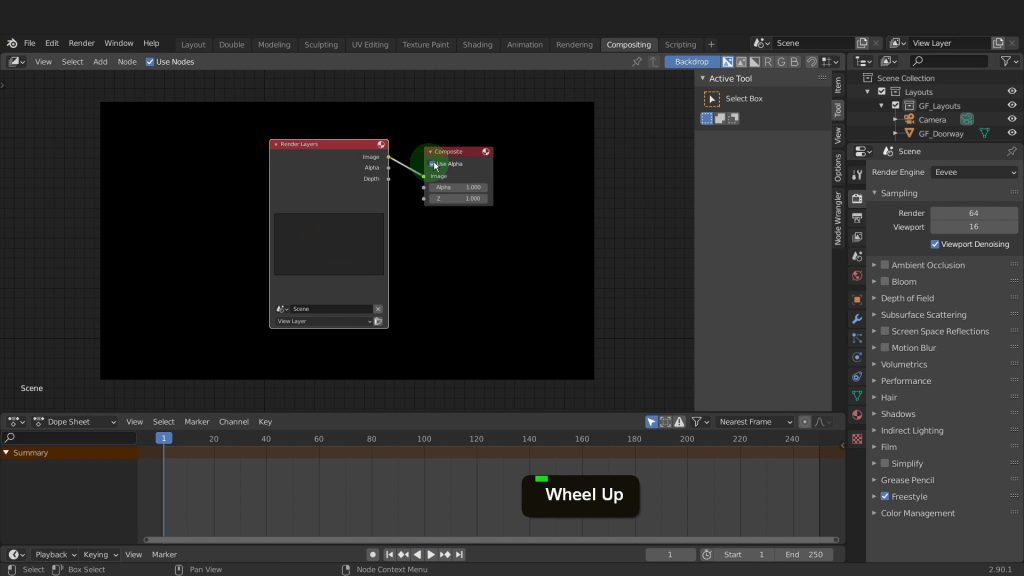
Lets switch into the compositing tab up top here. The first thing we need to do is put a check mark in use nodes. That way we can combine both the blender render and the MeasureIt render together. This is the default node network. It contains a view layer. The view layer is what is being rendered from the scene camera. Then the composite node. This creates the final output.
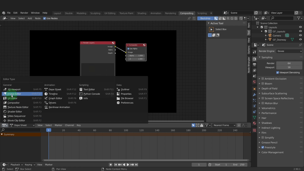
We need to add the MeasureIt render and combine here to be composited in the final render. We can do that by first clicking in the editor type and switching this to be an image editor.
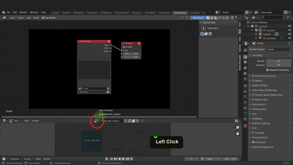
Then over in the image drop down choose the MeasureIt render. I can zoom out a little. It is hard to see as we only have a few dimensions added over the transparent background. I can left click and drag this image into the node editor.
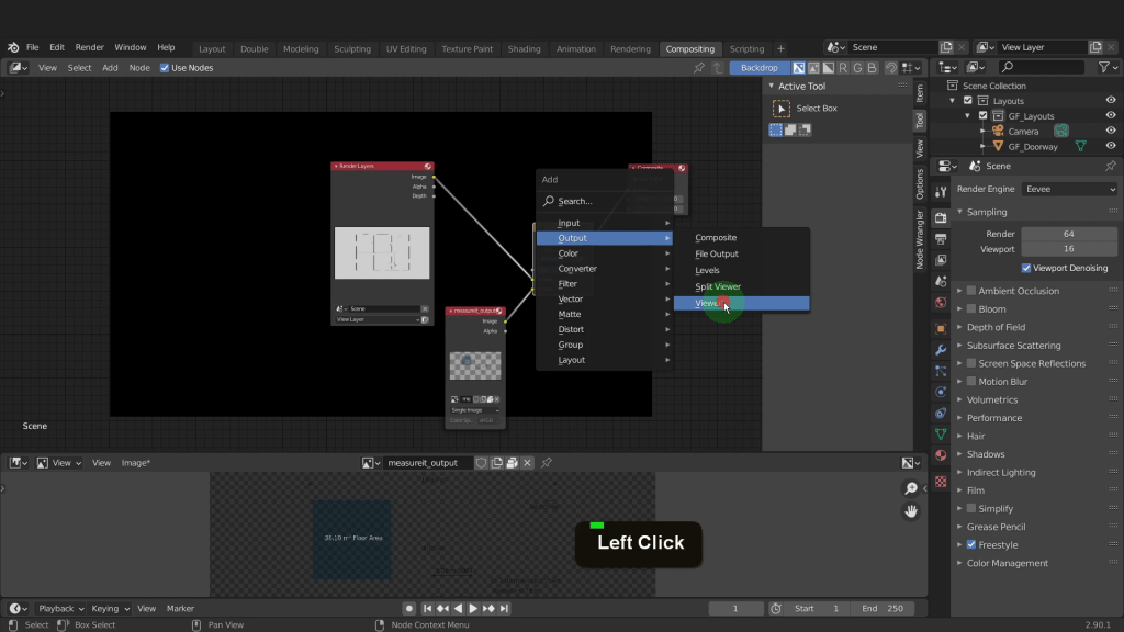
Drag the composite node over here. Press Shift + A and from the colour menu we can add an alpha over node and drop that there.

Drag the output from the render layer and plug this into the top image input on the alpha over node. Now drag the output from the MeasureIt node and plug that into the bottom image input of the alpha over node here. Take the result of the combined network and plug this into the composite node. We can add in a viewer node and view this here. Press Shift + A and from the output menu add a viewer node. Place that here. Take the result and plug this into the viewer input.
Press V to zoom out and Alt + V to zoom back in. What we see here will be the final result when we render. So if we come to the render menu we can click render image.
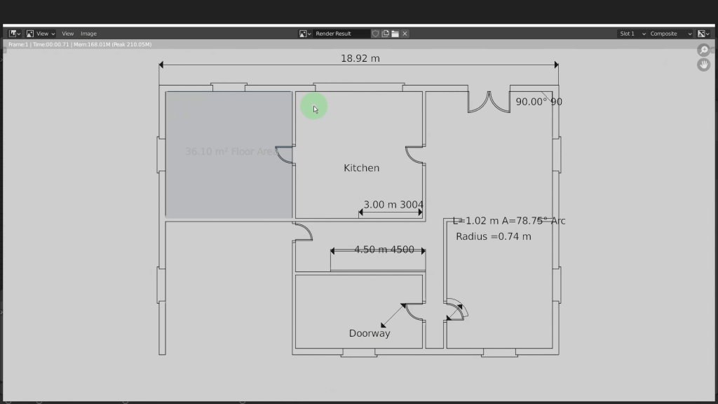
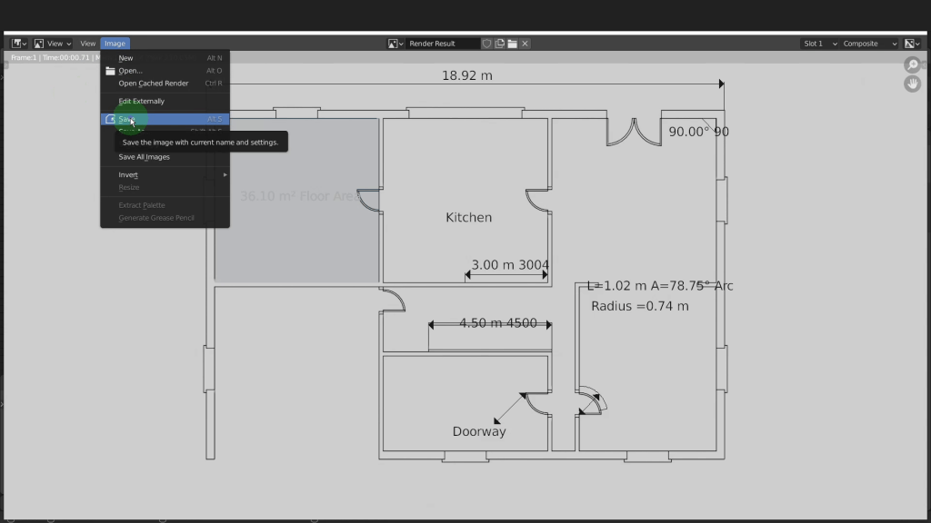
Now both the blender Eevee render and MeasureIt have been combined. If you want to save this render come to image and from here you can save it to a location.
That is the process of using the MeasureIt add-on to add dimensions to the layouts and combine for a final render. For more click the link for a more in depth course on Udemy.
