Introduction
This post is a simple guide for new users of the Blender 3D software. It includes some practical exercises the reader can follow along to. The exercises provides a “learn by doing approach” that is fundamental to understanding and mastering Blender. The first section provides information on the different areas within Blender when you first open the program. Here we quickly cover the main areas and their functions. The secret to Blender is gaining an understanding of the process, and theory, and by putting that understanding into practice, practice, practice. You can quickly go through this book in a day and the reality is most people don’t have a whole lot of time to spare. If you assign 30 minutes to an hour a day and follow the exercises, then repeat those exercises until you no longer need the book. This will give you a strong foundation in understanding the fundamentals of Blender.
Getting Started
You may already have a copy of Blender installed on your computer. To get the latest version of Blender visit www.Blender.org and click the Download button. This will bring you to the download page. Here you can simply select a Blender suitable for the operating system you have installed on your computer. There are three supported, Windows, Mac and the Linux operating system.
Blenders user interface
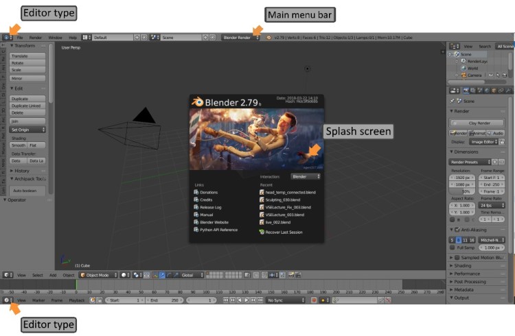
When you start Blender the program will display the current splash screen. The splash screen allows you to open a recent project, link to useful resources or copy saved setting from a previous version. If you are coming from Maya or 3Dsmax you can chose the button configuration of either program. To exit the splash screen you can simply click into the 3D view or hit the Esc key.
Getting Set up
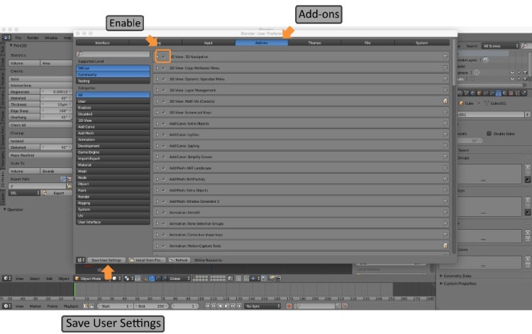
Blender uses add-on, a feature that extends its functionality through the use of scripts. These pieces of software code written in python can be enabled or disabled by going to:
File > User Preferences > Add-ons > Enable the Add-on by clicking and placing a check mark inside the box. The Add-on will now be activated once you select Save User Settings. Some Add-ons are switched on by default but please note the following add-ons need to be enabled to follow along to the exercises in this book:
Go to File – User Preferences – Add-ons: Enable Mesh: LoopTools
User Interface: Pie Menus Official: Enables short cut keys for efficient workflow.
Input Devices and Add-ons
The basics requirements to use Blender successfully are a 3 Button Mouse with scroll wheel and a Keyboard with Numeric Keypad. For keyboards without Numeric Keypads please follow the instructions below. Blenders default mouse select mode is with RMB (Right mouse button). To switch this to LMB (Left mouse button) go to:
File > User Preferences > Input > Select with > Left.
For keyboards without a Numeric Keypad go to:
File > User Preferences > Input > Emulate Numpad > Enable this option by clicking and placing a check mark inside the box
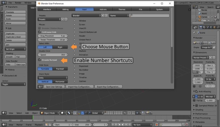
Note: After making changes in User Preferences always Save User Settings before exiting to update those changes.
The Default screen layout
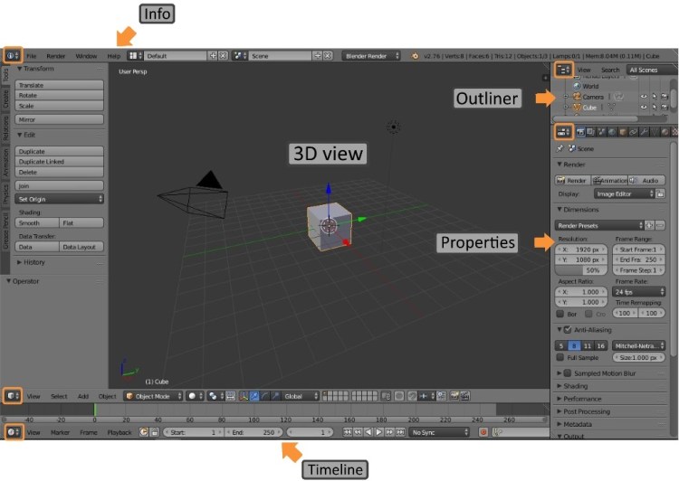
Blender’s default screen layout (pictured below) is highly customizable and is arranged into 5 areas containing 5 editors.
The Areas form the screen layout and contain the Editors. They can be dragged out or squeezed into an arrangement that best suits the user’s workflow and interface needs.
Editors consist of a header and one or more region. Headers are horizontal panels top or bottom containing menus and commonly used tools.
Regions contain buttons, menus, and check boxes. These can be rearranged to the user’s preferences.
The Editors
The Outliner Editor lists alphabetically by default every object within your scenes. Here you can easily maintain control of an objects visibility in the scene or during rendering. Here you can double click an object to rename, select it or delete it. In a large scene with many objects press the period key to quickly bring the outliner window right to that object. To avoid accidentally selecting or modifying an object in a scene you can make it disable its selection option.
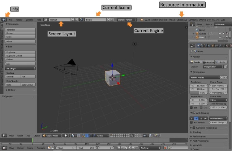
The Info Editor by default is displayed horizontally across the top of the screen. This editor contains the main menu bar displaying your current screen layout, current scene, current engine and resource information.
The Timeline Editor runs horizontally along the bottom of the screen and provides a visual display for the placement of key frames. These key frames store an object’s properties (position, scale etc) at a moment in time, allowing for interpolated animation between a second key frame.
The Properties Editor stores data for the active object and current scene. We will take a closer look at each tab on the Properties Editor later in this book.
The 3D View is your view to the virtual environment controlled with a combination of short cut keys and mouse button inputs to model, composite, animate, and edit within. You can select an object inside the 3D View with the LMB (Left mouse Button) unless you have chosen the RMB (Right Mouse Button) as the selection method. Press and hold the MMB (Middle Mouse Button) to rotate the view or roll the MMB to zoom in and out. The RMB places the 3D Cursor at a point in 3D space. The default 3D view contains the objects pictured below. These include the Camera, Lamp, 3D manipulator, 3D Cursor and the default Cube.
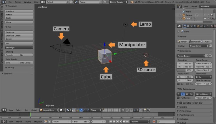
The Objects within the 3D View
The Camera object within Blender acts much like a real world camera. The rendered scene displayed from the cameras view can be outputted as images or video. With the Camera selected the properties editor Header contains the Camera’s settings. The lens type, focal length and depth of field settings etc can be adjusted here. Everything created in the 3D view will be displayed with the camera either as an image or image sequence. For this reason it is important to understand how the camera is controlled.
The default Cube is a mesh object and one of a number of primitive mesh shapes you can begin modelling with. Press Shift + A (Add menu) to view or add the other primitive mesh shapes.
The Lamp object is used to add light to a scene. There are four lamp types supported in Blender each one offering unique shadow and shading options. Lamps can be easily moved, duplicated and controlled within the scene. The properties editor header has the settings related to the lamp.
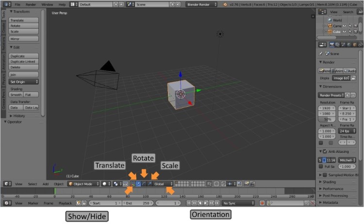
The Manipulator has three separate icons to represent each type of transform option currently selected. These transform options are Translate, Rotate and Scale. Used together or separately and accessed through the short cut keys Ctrl + Spacebar they provide a way of manipulating certain parts of the mesh quickly. You can change the orientation of the transform manipulator using the transform orientation menu. These options allow the object, its faces and edges to be edited in a variety of different rotations relative to themselves or the global orientation.
The Tool and Properties Shelf
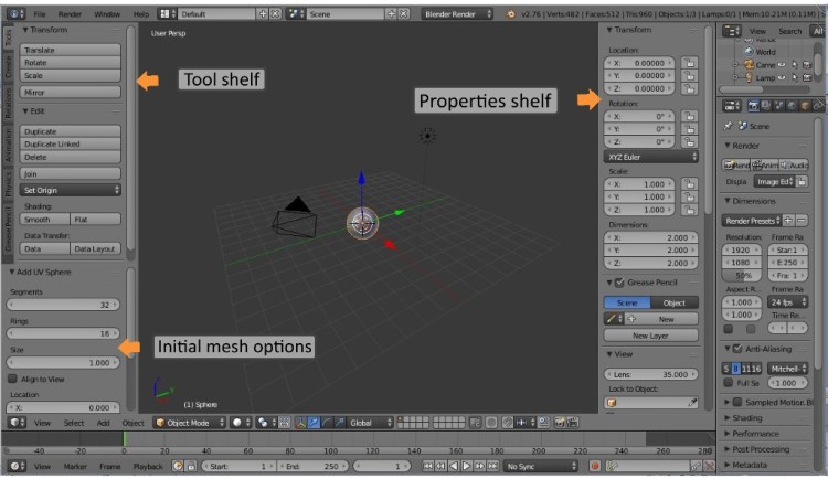
The tool shelf is located on the left hand side of the 3D editor and can be accessed by the short cut key T. This shelf contains tools that you will access frequently either from this area or by the use of short cut keys. The tool shelf options will change depending on the mode selected (Object mode, Edit mode etc).
When adding a new mesh to the scene initial mesh options become available on the tool shelf for that mesh. Here you can make any modifications to the default mesh before continuing. Please note that once any modifications are made to the mesh in the 3D view, e.g. transform, scale etc these initial options on the tool shelf will no longer be available. Any further modification will have to be performed in Edit mode.
The properties shelf is located on the right hand side of the 3D Editor and can be accessed by the short cut key N. The properties shelf has transform data for the selected object. The location of the 3D cursor can be controlled here. The display options for the scene, such as the grid floor and relationship lines can be controlled here. It also has scene shading options that can be used to improve visibility while modelling, for example. You can add background images to the scene to aid in the modelling of objects etc. The properties shelf data will change depending on the mode selected (Object mode, Edit mode etc).
Object Interaction Mode
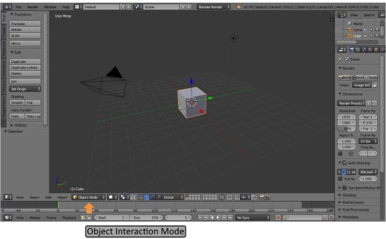
By default Blender begins in Object Mode. Blender is mode based and each mode within Blender has a specific function. Modes can be accessed through the shortcut key Tab once an object has been selected. This shortcut displays the Object interaction menu. The remainder of this book will be dealing with Object mode and Edit mode. Edit mode is where an object will be modelled into the desired shape. In Edit mode only the selected mesh object can be edited. Objects can be joined and edited together or parts of an object can be separated to form individual objects.
Unit of measurement
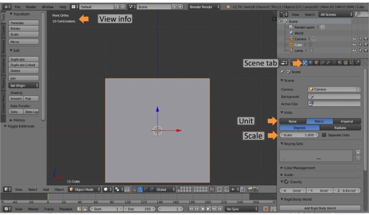
To set up the unit of measurement in Blender go to the Properties Panel and select the scene tab. The unit panel contains the unit type. By default the units are set to blender units with a scale of 1.
The image above shows the cube in front orthographic view. (Press 1 for front view, press 5 for orthographical view, and roll the mouse wheel to zoom in.) You will notice the screen is divided into grids of equal length and height. The cube on screen measures 2 meters and equal in length to two large grid divisions, each one measuring 1 meter. Zoom in further to reveal each grid divided into ten equal parts, each measuring 10 centimetres with these divided into 1mm divisions.
The view info is located at the top left hand side of the screen and displays the current view type and unit range.
Mesh Selection Mode
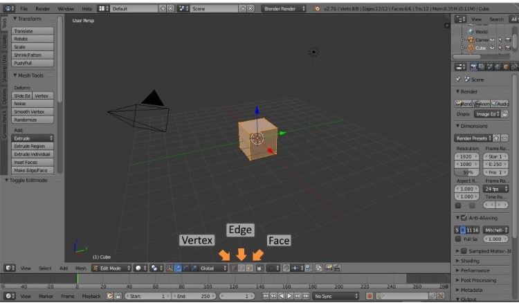
The first picture above shows the selected cube in Edit mode (With the cube selected in object mode press: Tab > Edit mode). You will notice the header of the 3D view will change to include Vertex, Edge and Face select.

Take the cube in the second picture as an example of selection methods within Blender. The default cube is a mesh object consisting of three basic elements. The Cube has 6 Faces, 12 Edges and 8 Vertices. The vertex is a point in 3D space while 2 connected vertices form an edge and four edges connected form a face. Each element of the structure Face, edge and vertex are used to edit the cube.
Viewport Shading
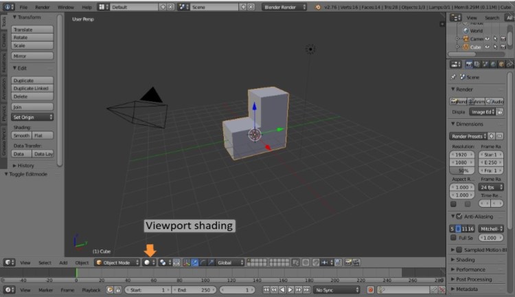
The View port Shading menu (Pictured below) and set to solid as default, can be accessed through the shortcut key Z. The shading menu options display the object depending on the material applied and or the lighting setup. The most commonly used shading options when modelling are solid and wireframe shading.
The 3D Cursor
The 3D Cursor is Blenders placement and pivot tool. The properties shelf holds the 3D Cursor panel with its x, y and z coordinates. To accurately place objects within the scene or to one another use the snap menu Shift + S.
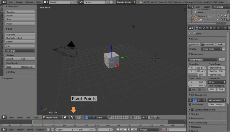
Pivot Points
Pivot Points allow for the rotation, scaling and mirroring of objects around a point in space. The Pivot Point menu provides a list of 5 to choose from each with their own uses. The Medium Point is the default Pivot Point, uses the center mass of an object for determination and is the most commonly used.
Layers

Layers are used as a way to separate objects within the scene and provides the user control over how an object is lit, how forces affect them and how they are rendered and the properties applied. In this way layers help organize the objects within the scene allowing efficiency and creating the ability for uncluttered workflow. The Active layer has a darker shade when on. When an object is selected a small orange circle indicates the layer the object is placed on. To move an object to a different layer select the object, press M and select the layer you wish to move it to.
Proportional Editing
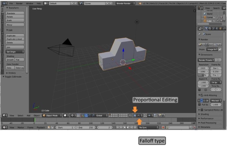
Proportional Editing Shortcut key “O” is a transformational tool for editing faces, edges and vertices. Using proportional editing on one or more parts of the mesh causes connected mesh elements to be affected depending on their location relative to that element being transformed. Mesh elements will be affected greater or less depending on the area of influence being exerted. The area of influence can be adjusted with the Middle Mouse Button. Proportional editing allows for smooth deformation of the mesh without leaving bumps and uneven patches that can happen when using the normal transformation options. Proportional editing has Falloff options that provide many ways to deform the mesh. The smooth option is set as the default option.
Snap Options

There are two Snap features in Blender. The first one we discuss is contained on the 3D Editor’s Header and is represented by the magnet icon. This feature is referred to as Snap during transform and when enabled the selected object will translate, scale or rotate in increments based on the zoom level and the element selected. Snap is set to increment as default and can be changed to the other options through the menu.
The second snap feature allows your selection or cursor to be placed at a chosen point by using the shortcut keys Shift +S or from the 3D Editor Mesh menu Snap. This option is very useful for setting origin points of objects or accurately adding mesh objects to a predetermined point in the scene.
The Properties Editor
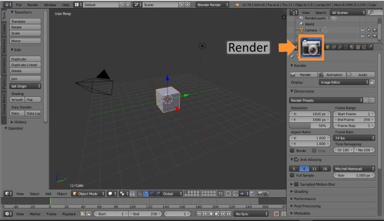
The Properties Editor has a row of icons displayed on its header and used to change properties for the active object and active scene. The first is the Render tab and allows control over the render output properties. The options include the render button that will render the current frame and the animation button that will render all frames in the current frame range. Other options include setting the image size, the image quality, or when setting up an image sequence, the frame rate. In order to render the scene must have an active camera.
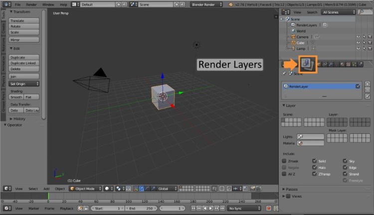
Render Layers allow you render certain layers of your scene separately. The advantage to this is in compositing where you can adjust individual elements differently. This also allows you to re-render individual layers rather than having to waste time rendering everything in the scene.

The Scene tab contains properties relating to the active scene including units, physics and colour management. Also switch between cameras within the scene.
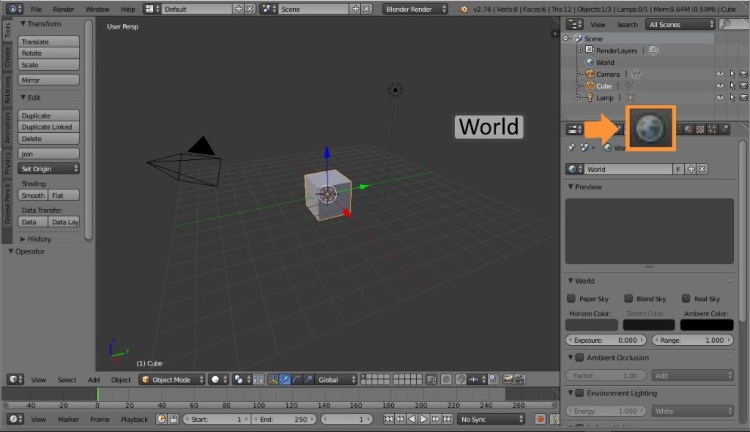
The World tab provides properties for the environment lighting, ambient occlusion, mist and sky colour. Depending on the render engine used, the options for the world settings will change. Here you can add HDR images for effective lighting.
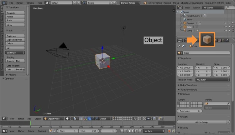
The Object tab displays data for the selected or active object including transformation, display and duplication setting.

The constraints tab provides the ability to control an object’s behaviour with tracking, transformation and other aspects of the relationships with other objects within the scene.

The Object Modifiers tab provides time saving operations to complicated tasks such as subdividing the surface of an object, adding a mirror modifier to duplicate in real time the modifications to the mesh on the opposite side. They also include simulate modifiers

The Object Data tab contains information specific to the current object such as vertex groups, shape keys and UV Maps etc.

The Material tab allows you to set up material for an object or part of an object. Depending on the render engine chosen the results will vary. With the cycles render engine enabled the nodes tabs provides a graphical node setup.
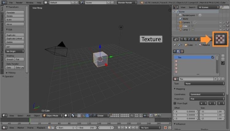
The Textures tab provides the mapping options to apply a texture to a material. The texture can be added to display specularity, reflections, or a pattern with apparent 3-dimensional depth.

The Particles tab controls any Particles systems deployed in the scene. There are two main types of particle systems you can choose from, Emitter and Hair, each with their own unique properties. Particles systems can be used to simulate hair, fur, grass or birds and fish. Particles systems are emitted from the selected mesh object up to a maximum of 100,000 and each mesh may contain many particle systems. Particle systems can be influenced by force fields etc and require large amounts of computer memory.
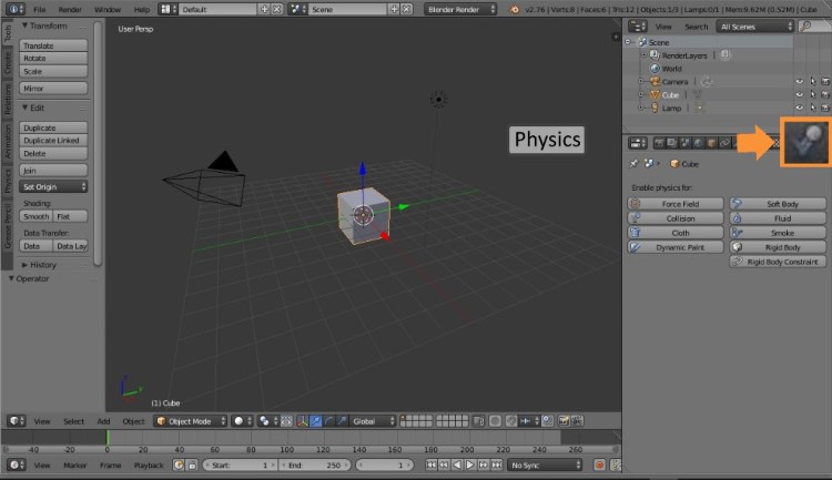
The physics tab has controls for simulating real world phenomena in Blender. With an object selected you can choose from a range of options each with their own unique properties.
