Introduction
In this post we’ll be rigging & animating a robot arm asset in Blender. You’ll find the robot arm demo file here, if you’d like to follow along. The post is also available as a video tutorial. Check out my character Modelling & Rigging course on Udemy for more indepth training.
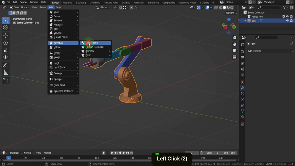
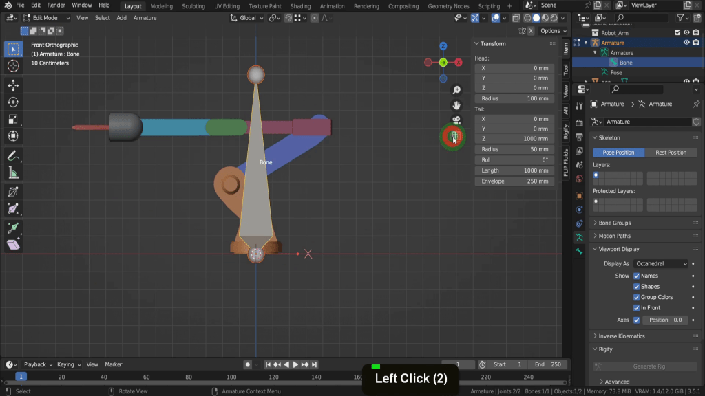
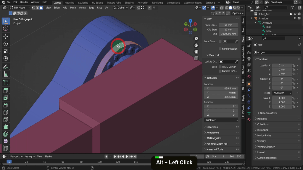
Rigs are made up of a series of interconnected joints, known as a hierarchical chain, which defines the range of motion for the 3D model. These joints are controlled using a system of controls, and allows animators manipulate the model to create performances. In this example we can use rig this robot arm model. You’ll find this in the resource folder of the course called scene_02 _Rig. This model is colour coded with each part that we’ll bind to a bone a unique colour. Let’s come to the add menu, and down to Armature, and we can add a single bone.
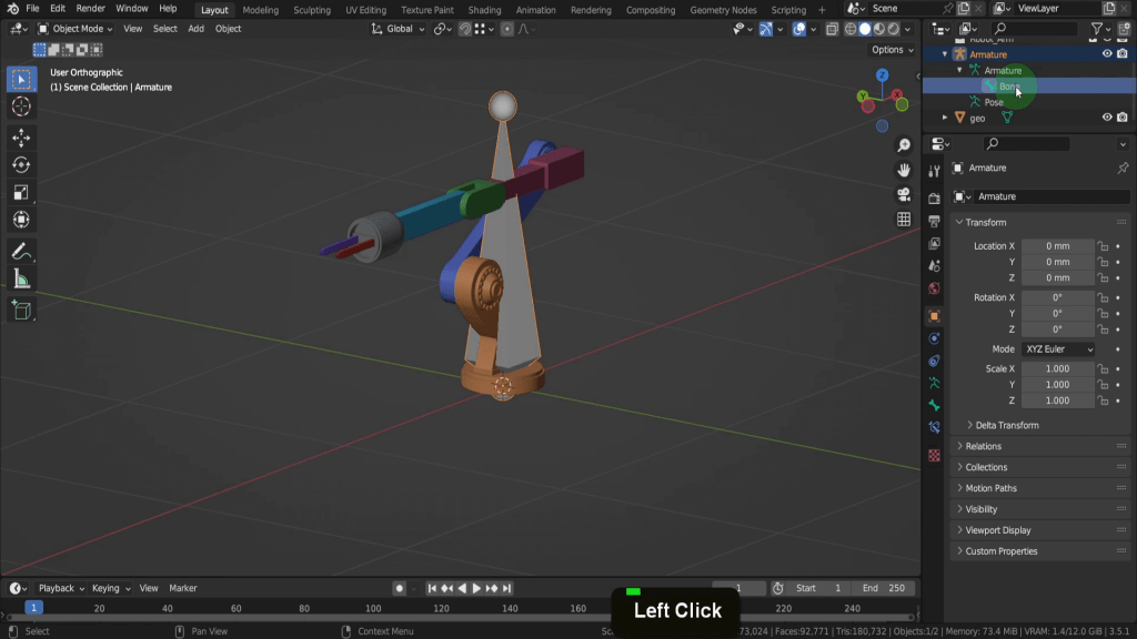
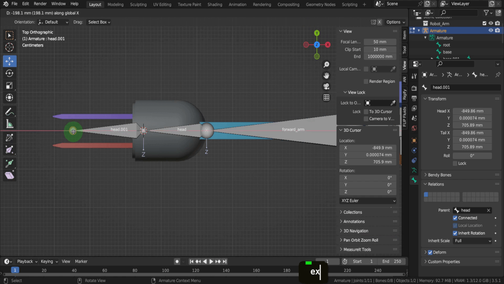
The armature object as we can see in the Outliner is a container or framework and a hierarchical structure containing the bones. So expanding the armature object exposes the armature and then the bone object inside.
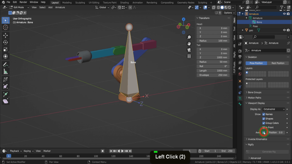
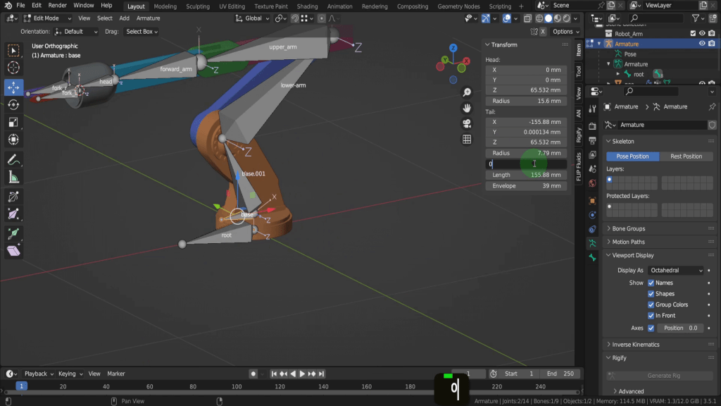
The bones itself is made up of two main components, joints, the head and the tail. If we tab into edit mode we’ll see that a little bit clearer up here in the transform properties. So you have the location of the head in the X Y Z, and the location of the tail with properties for its roll, length and envelope.
The connecting section between the head and the tail is a visual and if we come to the object data properties tab. And expand viewport display. Here you can change the display type, so for example we could have a stick. Can be less intrusive but more difficult tell the head from the tail.

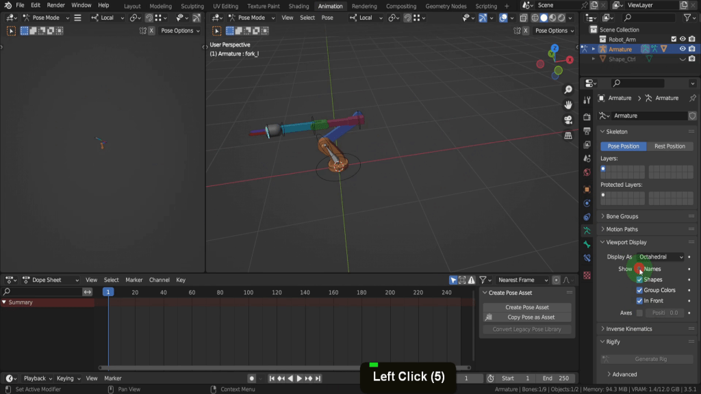
Let’s set this back to the default. We can check on “in front” and that makes the armature overlay other objects in the scene. You can also check on show names, and axes. These can be useful aids when learning to rig.
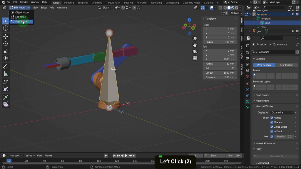
When translating the bone you should do so in edit mode. Try avoid scaling, moving or rotating the armature in object mode. The third mode available for the armature is pose mode.
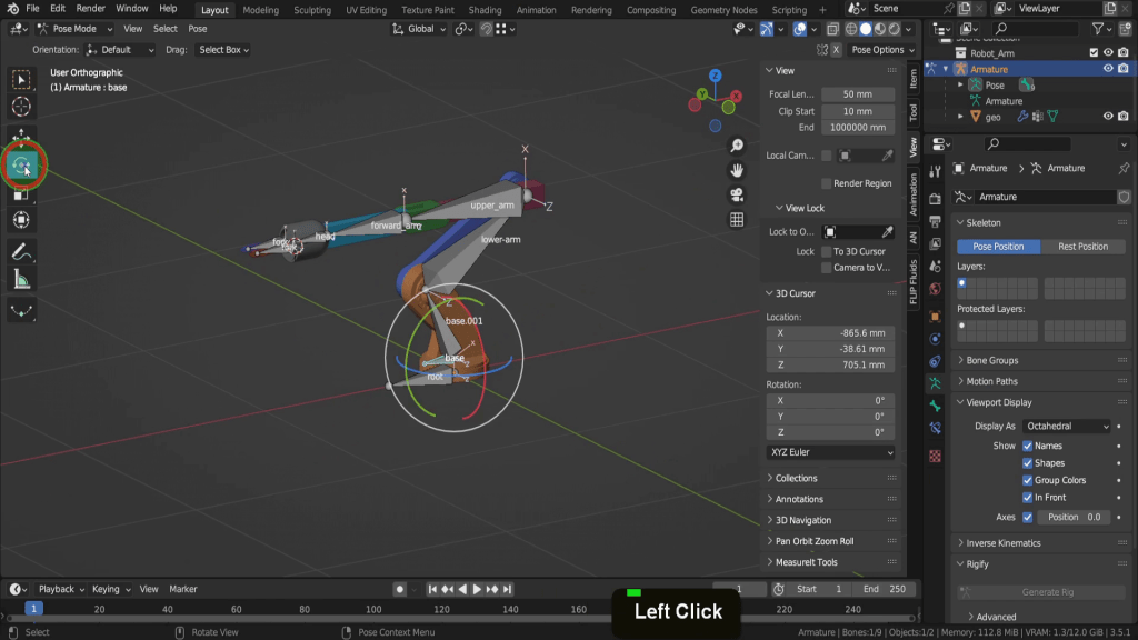
This is you can manipulate bones of an armature when posing or animating the character. Pose mode is used after the rigging and binding process so we’ll look at this mode later. Let’s start and rig up this arm so let’s come into a front view first. And we can make sure we’re in an Orthographic view with this button here.
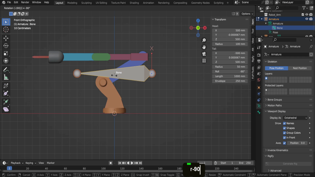
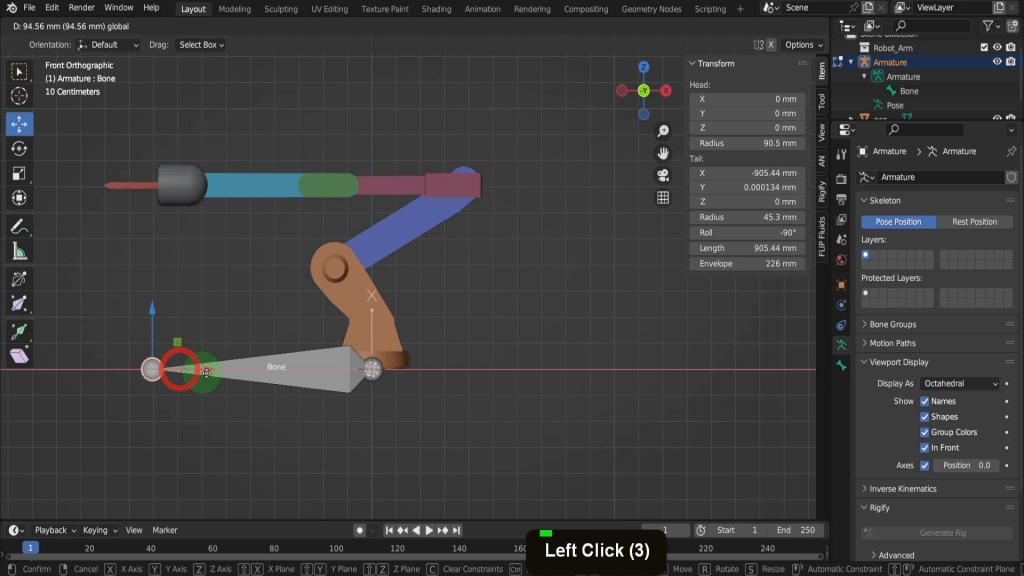
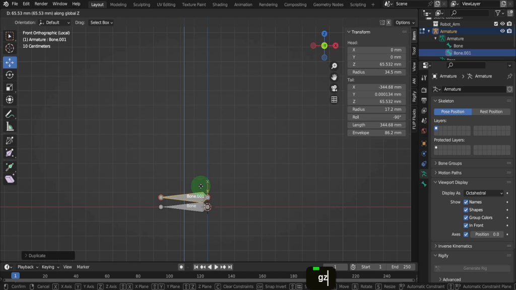
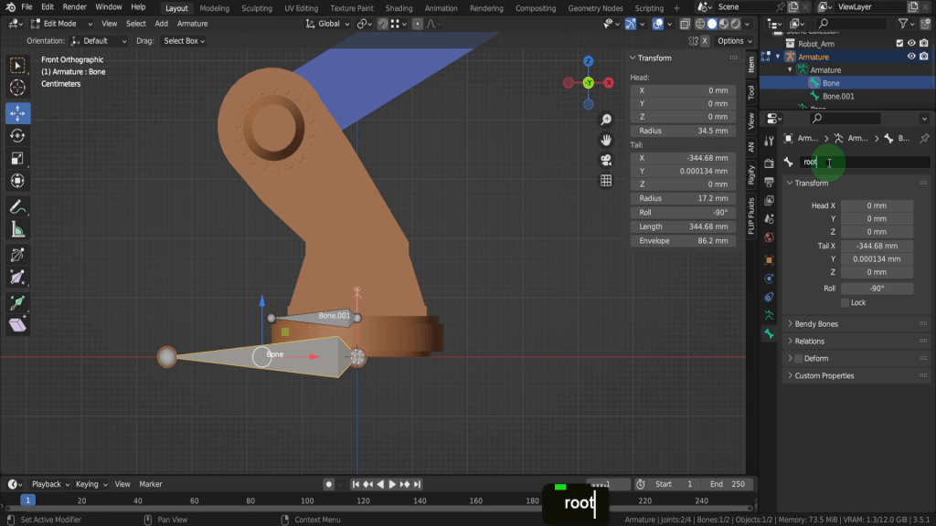
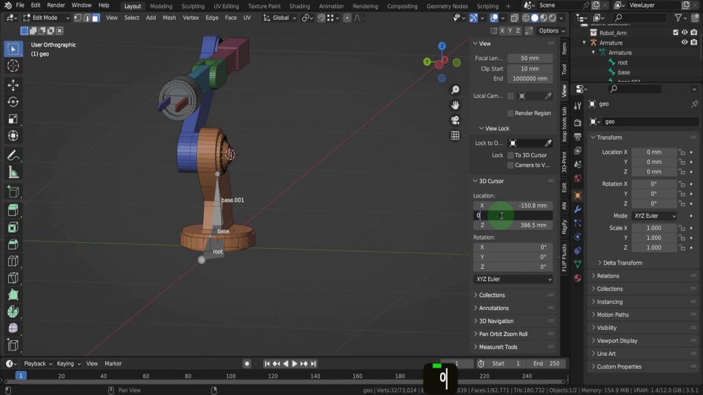
Let’s select the bone and this will be the root bone. We can press R input -90 and enter.
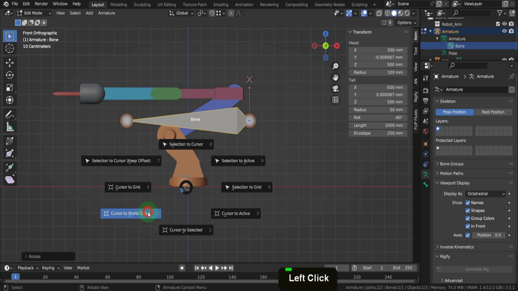
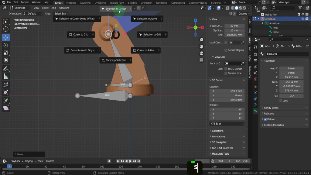
Let’s use snapping to snap the bone to the base of the arm and its origin. Incidently the origin point of this arm is at centre bottom of the its base which is also world zero. Generally you will want the origin of a character or asset at its base and the same position of the armature. We can snap the bone to the base so first if we press Shift + S, we can put cursor to world origin.
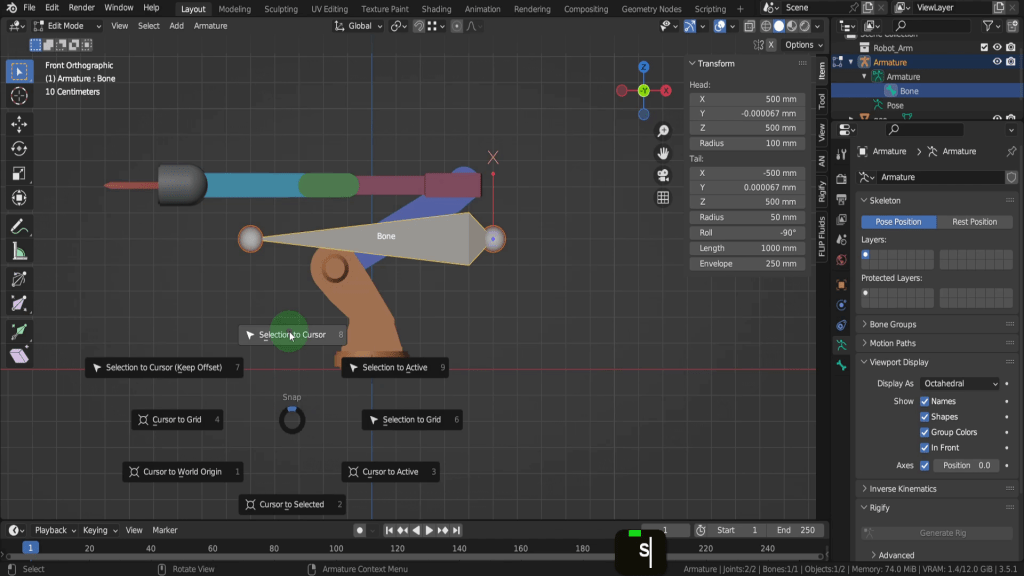
Then press Shift + S and choose selection to cursor.
That snaps the head of the bone to that position. If we come to the tool shelf we can switch on the Move tool.

That way we can just drag the tail back and reduce the bone in size.
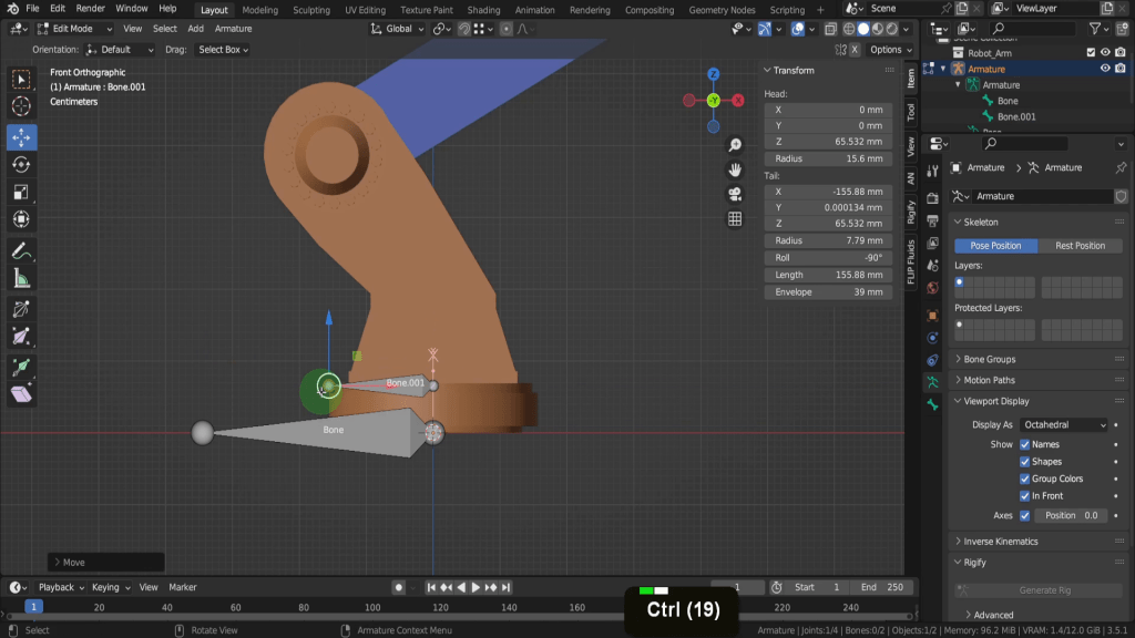
Let’s add the next bone in the chain. This will be used to control this lower arm section. Let’s actually press the forward slash key to isolate this Armature so you can see how this bone gets added.
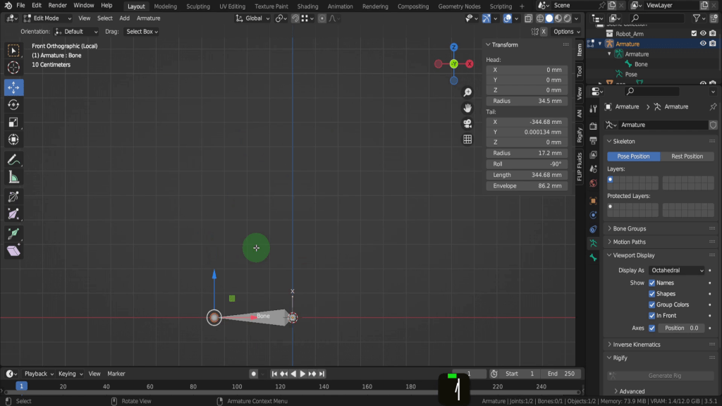
There’s are a couple of ways you can create the next bone in the chain. The first is with the head selected press Shift + A and create one this way.
That will create a bone from the head of the root bone. Another way if I delete this bone again with the head selected press E to extrude, press Z and restrict this to the Z axis.
Another way to create a bone is to duplicate an existing on. We can press X and delete this bone. Select the root bone and press Shift + D and right click to cancel movement. Then press G Z and drag this up a little.
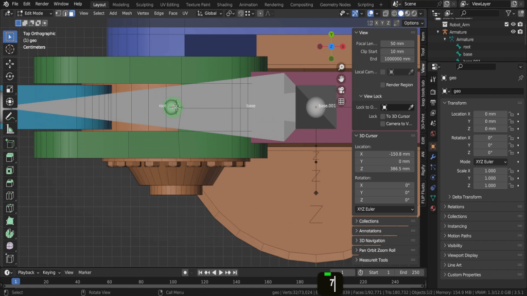
Lets press the forward slash key and return to global view. This remains centre of the base and away from the root bone. We can grab the tail and drag back, press Ctrl and snap to the outside of the base.
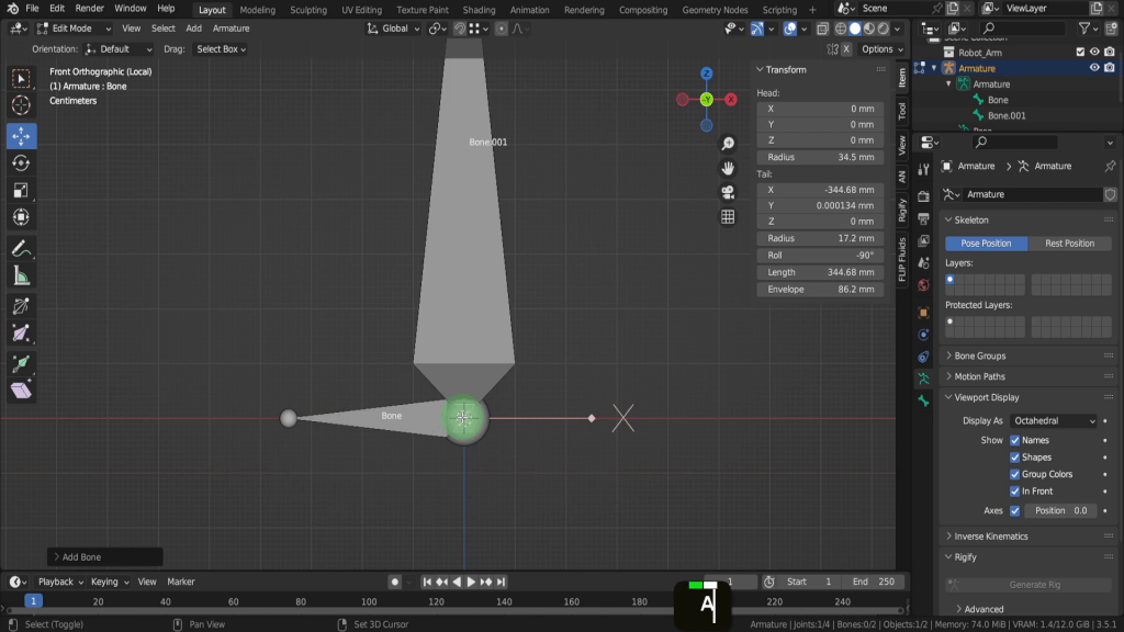
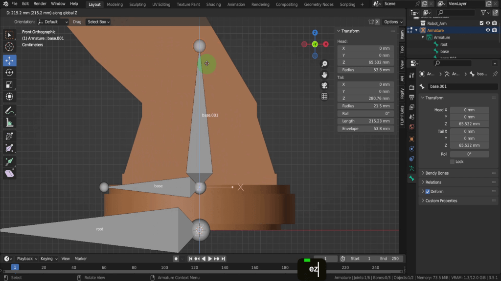
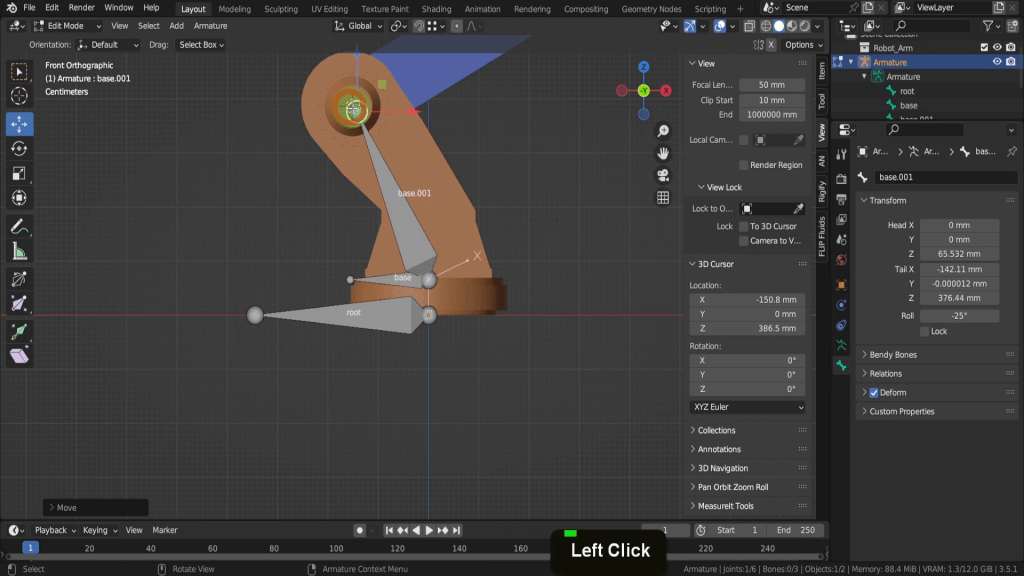
One distinction to make between these bones is that this new bone will be a deform bone, where as the root bone will not. Its an important distinction as deforms bones are the ones you bind to vertices and directly deform the mesh, whereas bones such as the root bone do not deform. The root bone is a reference point for the entire armature, the first in the hierarchy and doesn’t directly deform any vertices. If we open the bone properties tab here we can see the deform checkbox is on for this new bone, its on by default for all new bones. If we select the root bone we can uncheck deform.
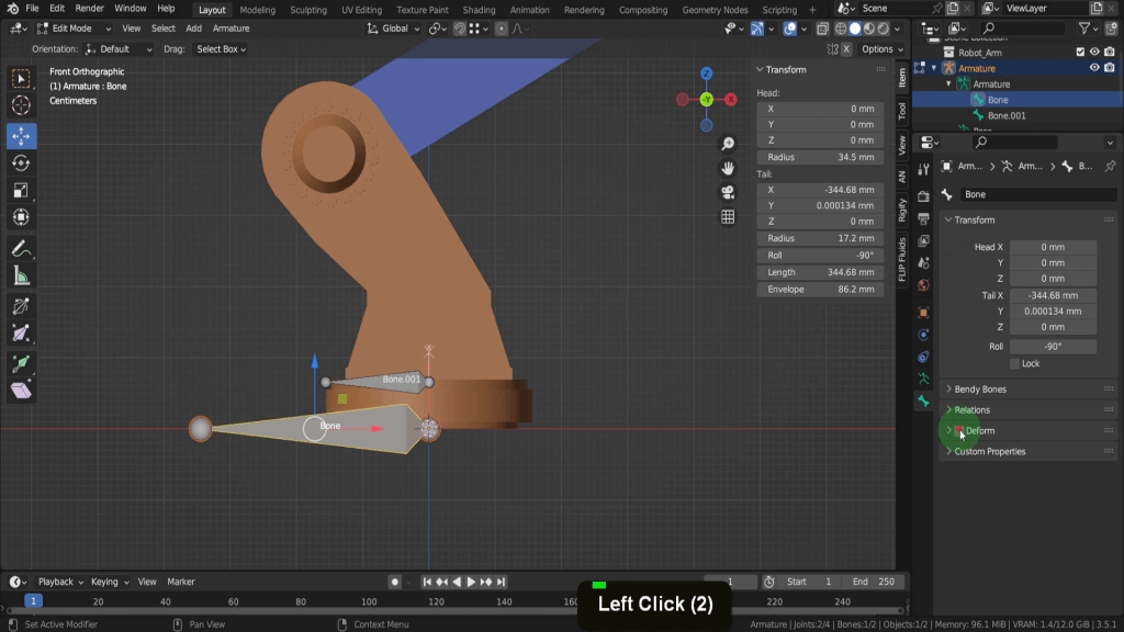
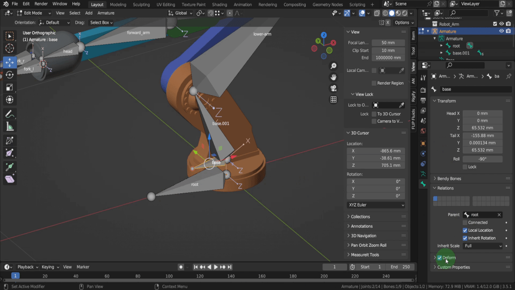
As we added each bone Blender adds a suffix “.001” so each name is unique. That’s helpful but you usually need more descriptive names, especially when binding the joints to the vertices. Knowing exactly where each bone is located and what vertices to bind to is important. If you select the root bone we can press F2.
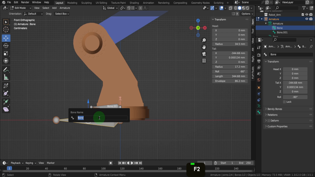
That brings up the name field and the bone can be renamed from here. If we right click to cancel you can also open the bone properties tab. Here we also have the name field so lets rename this “root”.
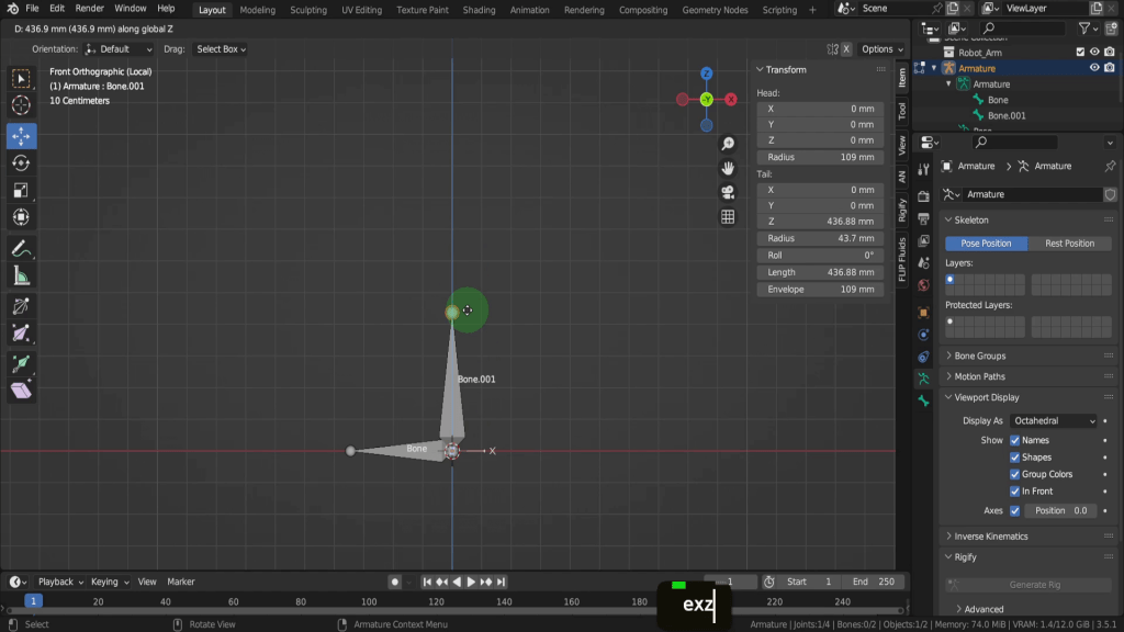
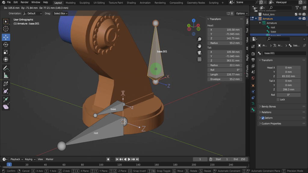
The next bone we can rename to “base”. Its important name bones, and to have a consistent naming convention throughout your rigs. That way when you pass off your rigs to animators or even when animating yourself the names make sense. Lets come back into a front view. We can select the head of the base bone. Press E Z and drag this up.
Lets rotate around in the scene. One thing you need to keep an eye on when adding bones, is the bone orientation. When we extruded this base bone maintains the root bones orientation. If I press G and just drag this away, you can see the axes icon and the Z axis are pointing in the same direction. And that’s what we want as we’re adding new bones, we’re looking for consistency in each bones orientation.
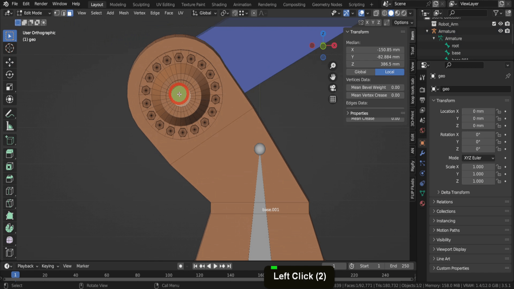
The next thing we need to do is get this tail of the bone into the correct position. So this next section of arm here will be pivoting from the centre, so what we need to do is find that point on the model and snap this tail to that position. To do that let’s tab back to object mode and we can select this model. Now let’s tab in here. The easiest way to do this is by selecting a centre vertex or in this case a face, so let’s switch to face select. Select the centre face and we can say that’s approximately centre of this round section here. This will be the pivot point from where this arm section rotates.
So let’s press Shift + S and we can put the cursor to selected. We also need to move the cursor back so its aligned with the bone and we can quite easily do that as the bone is at zero on the Y axis. So let’s open up the view tab. Here we have the cursor location and all we need to do now is in the Y field input zero.
That moves this back Center. So if we just come into a top view we can see that yes it’s aligned with this bone.
So let’s tab back to object mode. We can select the Armature and tab in here. Lets come into a front view. Press G and drag the tail close to the cursor.
Now press Shift + S and choose selection to cursor.
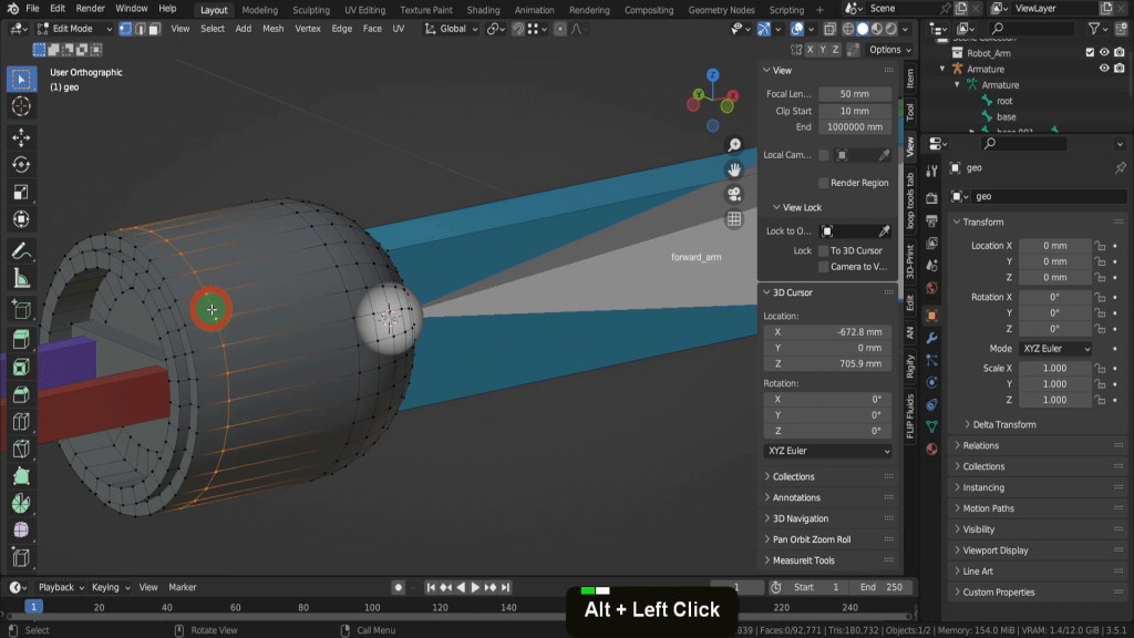
That moves the head into the correct position and what will be the rotation point for this next section of arm. Now we need the placement position for the next joint so let’s tab back to object mode. Select the model and tab in here. Let’s zoom in close here. We can Alt select this edge of faces here.
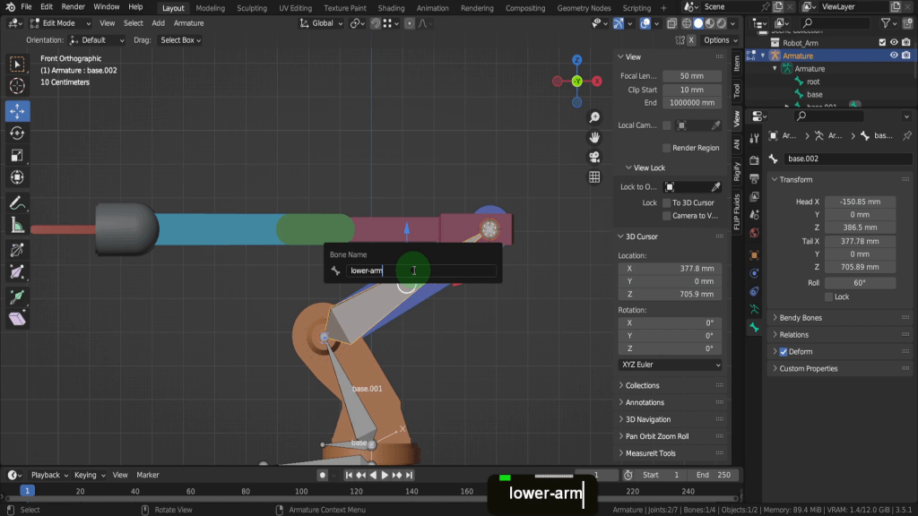
Press Shift + S and we can put the cursor to selected. Similar to before we need this at zero on the Y-axis and aligned with our armature. So let’s come to the view tab. In the Y location field let’s input zero. Now we can tab back to object mode. Select the armature and let’s tab in here. Let’s come into a front view as it’s easier see where the bone is placed. We can press E to extrude, press X to restrict it to the X axis and we can left click and just place that here. Press G and drag up close. Then we can snap this into position so press Shift + S and choose selection to cursor. Lets select the bone. Press F2 and rename this “lower_arm”. The previous bone “base.001” is fine name this as we won’t be binding this to any vertices. Its just a visual for the bone hierarchy.
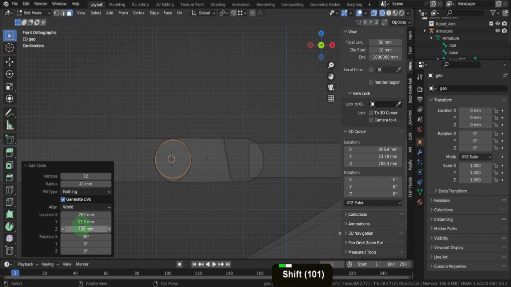
We can continue placing these joints so let’s tab back to object mode and we can select the model. Now tab in here. Sometimes you’ll come across areas like this where there’s no definite centre point. In situations like this we will try get it as exact as possible and where we determine it to be. Here we can add a circle and get an approximation. So let’s come into a front view. We can also press Z and switch to wireframe. Select the face here. Shift + S and put the cursor to selected then from the add menu let’s add a circle. In the properties box below here let’s expand this. Click and drag to reduce the radius and bring this in up to about what we are expecting here. In the X rotation lets input 90 and face this forward. Then adjust the radius to better match the size. Use the X and Z location fields to more the circle to the correct position. This looks like a good match right now.
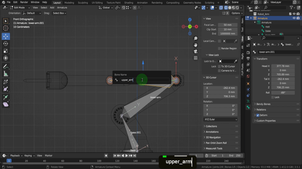
So let’s press Shift + S and choose cursor to selected. In the view menu, in the Y location field let’s input zero. We are finished with this circle so press X and delete vertices. Let’s tab back now and we can select the armature. No tab in here. With this joint selected let’s press E to extrude, X to restrict it to the X-axis and place that here. Press Shift + S and choose selection to cursor. Lets select it and press F2 and we can rename this “upper_arm”.
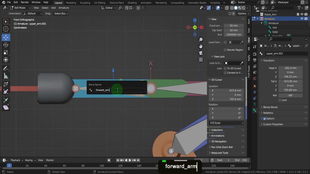
We can tab back to object mode and select the model again. Now let’s tab back in here. For this joint, this vertex here will be the rotation point. Press Shift + S and put the cursor to selected. We can switch back to solid shading. In the view tab if we look at the location Y this should be zero, so update that if its not exactly. So now let’s tab back and we can select the armature again. Now tab in here. Select this joint. Press E Y and drag this forward. Shift + S and put selection to cursor. Select it now and press F2. We can rename this “forward_arm”.
Now we need the next bone in this chain, so let’s tab back to object mode. We can select the model and tab in here. We really just need to place this close to the top so let’s Alt select this edge Loop here.
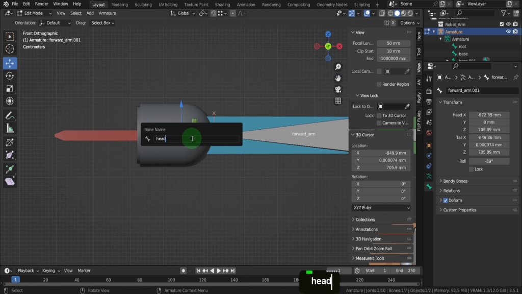
Press Shift + S and put the cursor to selected. Now we can tab back and select the armature, now tab in here. Come into a front view. Press E X and just drag this forward. Press Shift + S and choose selection to cursor. Lets rename this “head”.
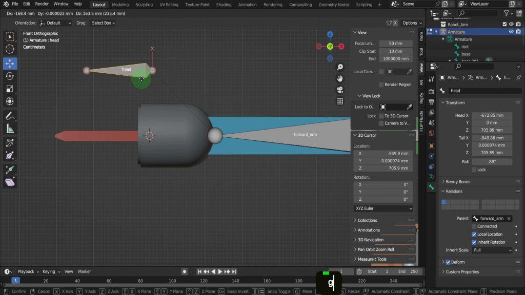
Let’s come over to the bone properties tab. Here we can see the parent bone is the “forward_arm”. We can also see that the check mark connected is enabled. This means that it’s directly linked to its parent bone, so when the parent bone is moved or rotated the bone will follow along. However when connected it cannot move independently. When this is disabled the bone can be moved independently, but it does remain a child.
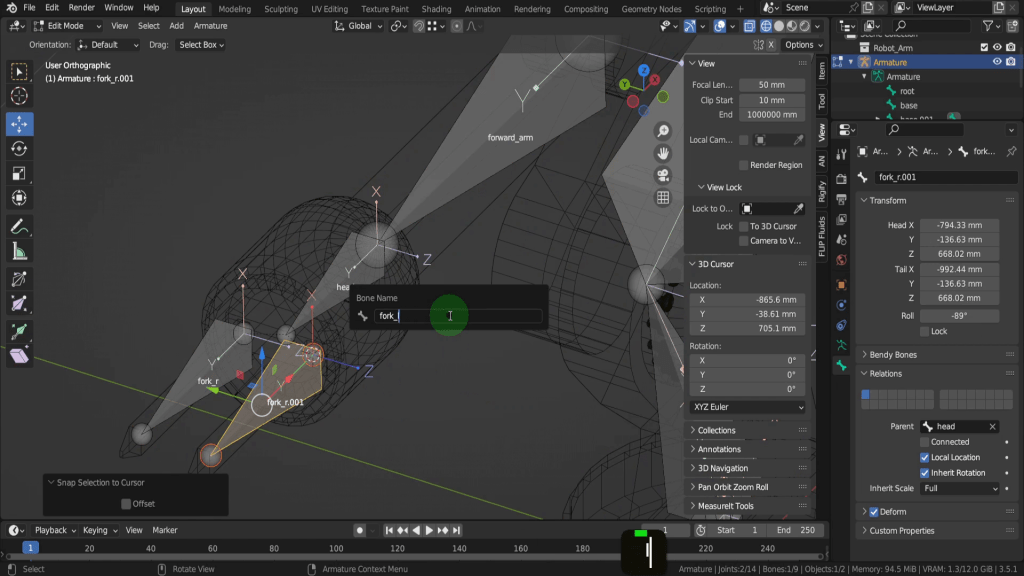
The next two bones in this chain will control the forks and will be disconnected so let’s look at creating these bones. Let’s come into a top view. We can press E X and drag away here. If we select this bone and press G it’s going to remain connected to its parent bone. So we can right click. Over in the relations area let’s uncheck connected. That way we can press G and this will move independently.
So let’s tab back to object mode and select the model and tab in here. We want to place this at the back of the fork here so let’s switch to wireframe shading. We can select the 4 back vertices of this rectangular shape here.
Press Shift + S and put the cursor to selected. Now let’s tab back to object mode and select the Armature. No tab in here. With this bone selected let’s press Shift + S and choose selection to cursor. We can rename this bone so let’s press F2 and rename this fork_r” to indicate this is the right side bone. Lets make a duplicate so press Shift + D and move this over here. We need to get the snap point so tab back and select the model and tab in here. Select the vertices on the opposite side. Press Shift + S and put the cursor to selected. Now tab back and select the armature and tab in here. Select the bone and press Shift + S and put selection to cursor. Press F2 and rename this fork_l. You also notice it keeps the parenting hierarchy with the head bone.
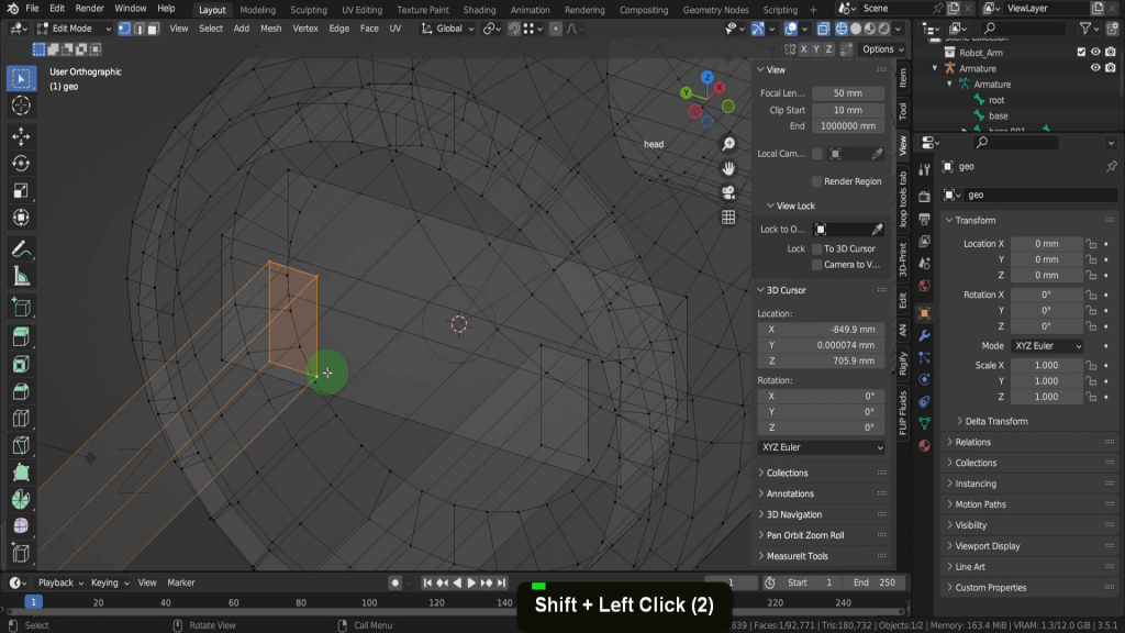
This next step can be known as skinning, weight painting or binding and it’s the process of associating the vertices, edges and faces of an object with the control objects, in this case the armature, and the individual bones. Each vertex is assigned a weight for a particular bone and how much influence it will have. Its a form of parenting, and once each bone is bound will deform a section of the mesh. So the base bone will control this base section here once the vertices are assigned, and then each section up along will will be controlled by the assigned bone. Before we move on to that process let’s first make sure the parenting hierarchy is correct with our rig. So if we begin with the root bone, in the relations tab this parent field is empty as this is the root bone and the first in the chain. Deform is also unchecked.
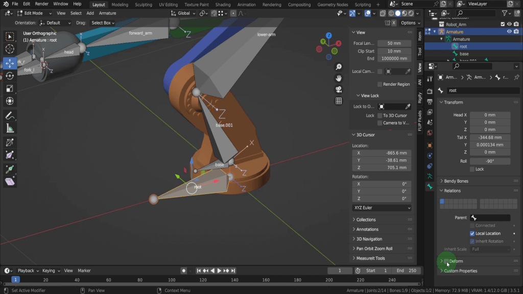
Select the base bone. Here we need to make sure the root bone is the parent. Also deform is checked on.
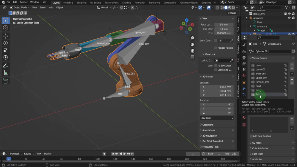
We can quickly select each bone and make sure the previous bone is the parent bone. These look good so lets tab back to object mode. If we select the Armature first. Then just drag select all objects. The armature is the last one selected so it’s the lighter colour and the active object. We use the parenting menu so we can press Ctrl + P and from here we can set parent to armature deform and choose with empty groups.
This will create vertex groups on the mesh, each named after a bone in the armature. These are empty groups so no influence has been assigned to the vertices. We will assign the influence manually and its a common approach when binding mechanical objects. Right now if we select the Armature itself and press G the entire object moves along so we know the object is parented to the armature. We can right click to cancel. Now if we select the mesh object we can go to the”Object Data Properties” tab. Here we will see a list of vertex groups with the same names as the bones in your armature. These vertex groups are empty, meaning they have no vertex weighting assigned yet but we can do that manually now.
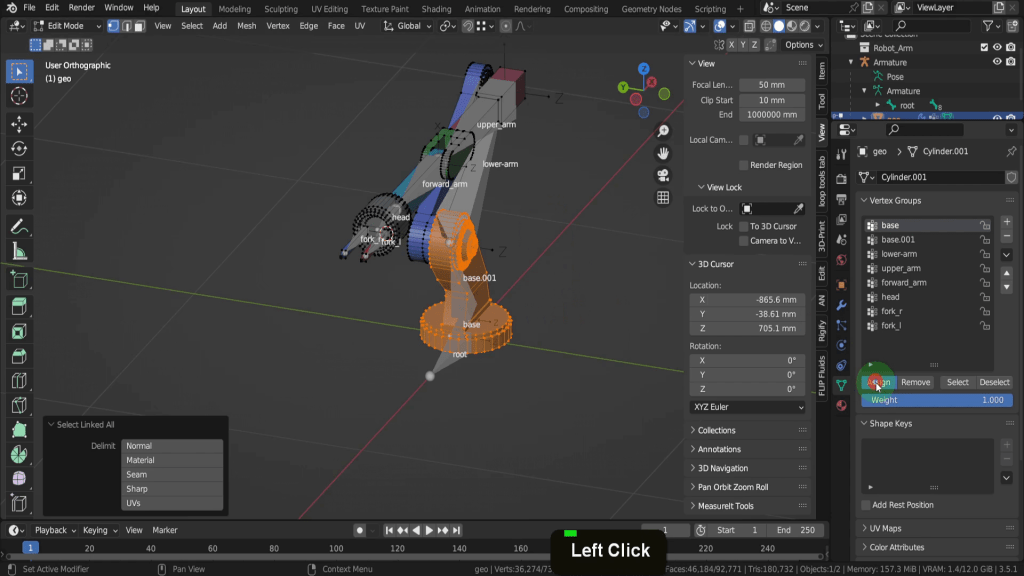
So lets tab to edit mode. The first thing we can do is press Alt + A and deselect any vertices. We don’t want any vertices assigned to the wrong bone. You’ll notice when in edit mode we get a few additional buttons under the vertex groups area. The first one is to assign the selected vertices to the selected group. The second is to remove any vertices from a group, then you can select the vertices of individual groups or deselect them. Beneath this is the weight value, so how much bone weight are you assigning the selected vertices.
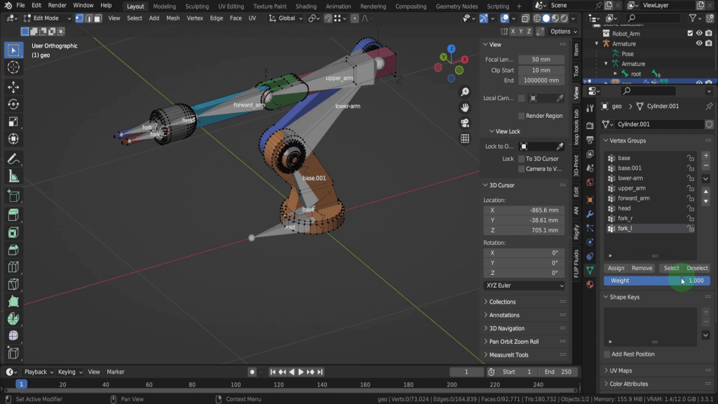
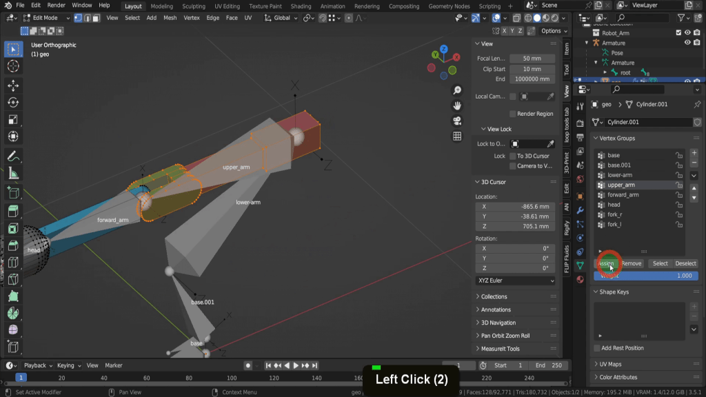
Let’s begin with the base bone. With it selected let’s come into the scene and we can hover on parts of the base object and press L to select them. We can also maybe Shift + drag select this section here with the individual nuts and bolts. Then press Ctrl + L to select linked and make sure all of these are selected. If we press G we can see this whole objects moves away as one.
So with that we can come over and click assign.
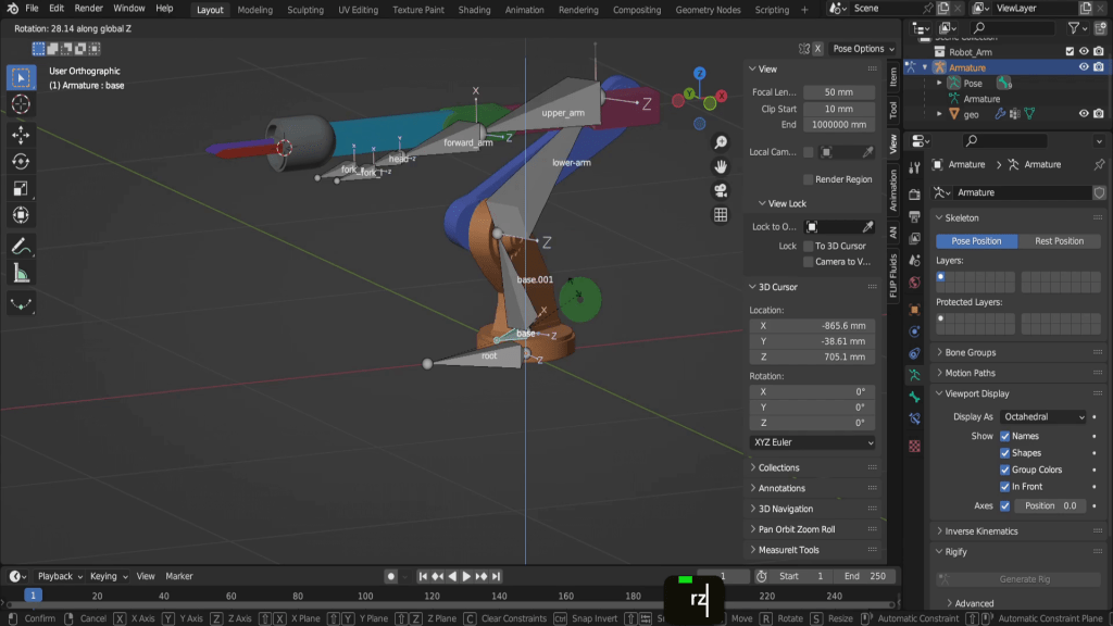
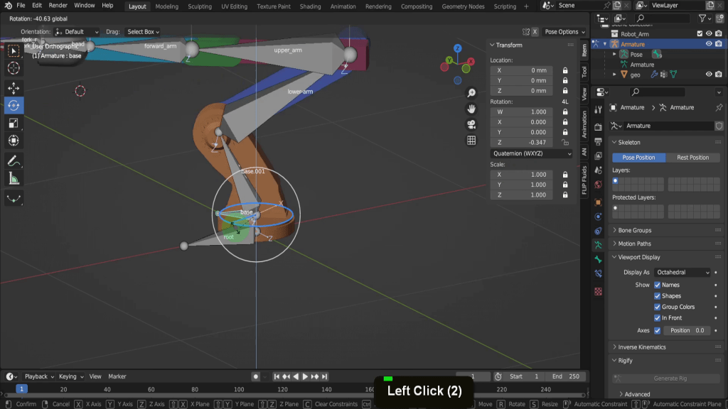
This assigns a weight of 1 the select vertices to the base bone. So to check the selected vertices are fully weighted we can first tab back to object mode. Select the Armature and then from the mode menu let’s switch into pose mode. Pose Mode is a mode used for working with armatures and posing rigged characters or objects. It allows you to manipulate bones in the armature to create different poses, animate the character, and control deformations of the mesh. In Pose Mode, you can move, rotate, and scale the bones of an armature, create keyframes for animation, and use various constraints and drivers to control the bones’ behaviour. If we select the base bone in here. Press R Z this bone will rotate the vertices we assigned. So the entire base of the object will rotate, scale or move along with the bone.
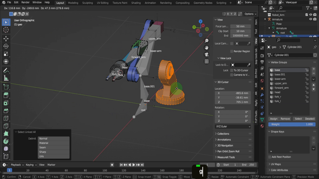
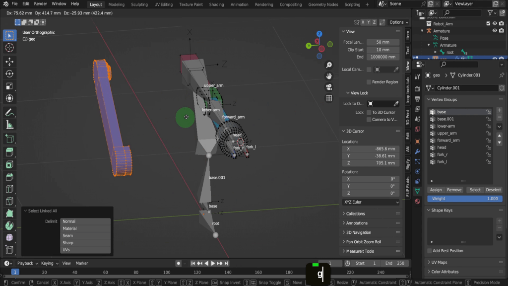
We can move on so let’s press Ctrl + Tab and come back to object mode. We can select the model again and tab back in here. With these vertices still selected let’s press H and hide them and make it easier focus on the remaining we need to bind. Lets come into a top view. We can also switch to wireframe shading. Let’s drag select this section here. Then press Ctrl + L to make sure all connected vertices are selected. We can rotate back around here, and also press Z and come back to solid shading. So if we press G this section of arm moves as 1 and we can be sure its all selected.
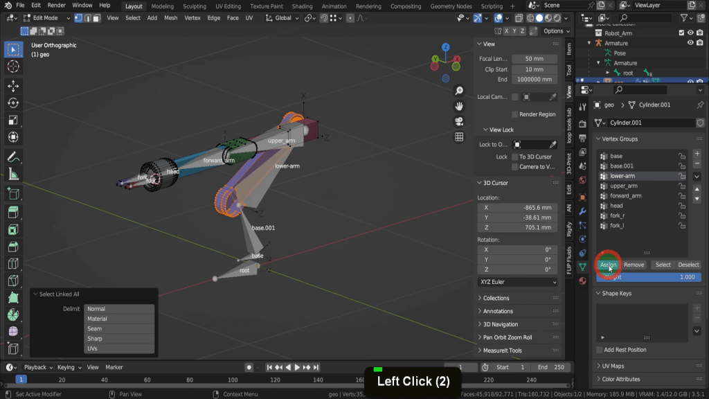
So in vertex groups let’s select the lower arm bone. Then we can click and assign the selected vertices to this bone.
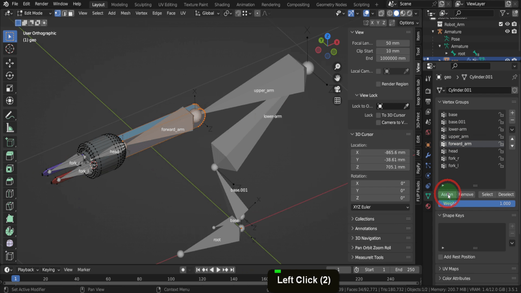
Let’s press H to hide that set of vertices. For the next bone we have these two pieces of mesh here. So let’s hover the cursor and press L to select both these pieces. Then if we select the upper arm bone we can click and assign these vertices.
Press H and hide this selection. For the next one let’s again press L to select this. We can then select the forward arm and click assign.
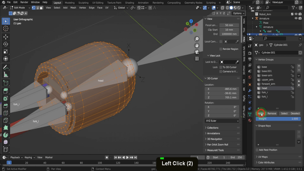
We can repeat this for the next section so press L to select all of this. We can also select this small piece out in front. This will need to move with the head bone as the two front bones will move horizontally. Now select the head bone and we can assign these vertices.
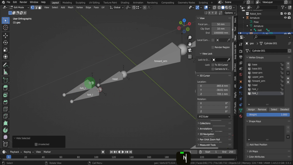
No press H to hide. That leaves fork r and Fork l so let’s hover on the vertices of fork r and select these. Select fork r bone and assign these vertices. Press H to hide this. Let’s quickly repeat that for fork L and we can assign these vertices. Then press H to hide this. So once all your vertices are hidden you can be sure they have been assigned to some bone in the Armature.
To begin we can press Alt + H to unhide all the vertices. Now let’s tab back to object mode. If we select the Armature we can press Ctrl + Tab and come back into pose mode. On the tool shelf we can switch on the rotation gizmo.
That way you can test each of the bones are controlling the assigned vertices. After you rotate the bones and need to reset to their default orientation, first press A to select them all. Then press Alt + R to reset rotation.
Alt + S will reset scale and Alt + G will reset any translation. If we select the base bone we can to test rotation. If we open the sidebar we will see this more clearly. We can open the sidebar and the item tab. In the Z rotation we can click and drag to rotate the base bone around the Z axis. This shouldn’t be rotating along this axis, so there is obviously an issue with the bone roll.

So lets tab into edit mode. Here in the roll field this is -90 so lets reset this to zero.
We can tab back now. Lets click and drag in this field now. This works as expected now and because this is the only axis we need to rotate this bone around, what we can do is use the lock icon and lock all other fields, including the location as this will avoid accidentally moving the bone out of position. Lock the scale fields also. So let’s lock all of these except for the Z rotation.
So that way if we select the rotation gizmo only the Z axis is available. I can right click to cancel. Also if you press R it will only rotate on the Z axis.
Now you can overwrite that by clicking and dragging in the fields here, but you usually don’t animate this way. The next bone, base.001 we don’t want to have the ability to move, rotate or scale at all, so we can click the lock icon and lock all location, rotation and scale transforms here.
We can move up along the chain to the next bone. This will rotate around the Z axis. So every other field can be locked. So if you press R to rotate it’s ever only going to rotate on this axis. Same thing with the next one, we can lock all of these except for the Z axis. So that way when you press R these are only going to rotate around the correct axis. We can continue and lock the rest up to the forward_arm. The head and fork bones will be a little different. So for the fork bones we can switch to the move tool. And up top in the transform orientation drop down let’s switch this to local.
So we just want these to move in and out around the Z axis. So every other field here can be locked. So that way if we press G it’s ever only going to move across on the Z. We can do the same thing for the second bone here and lock all other axes except for the Z location field.
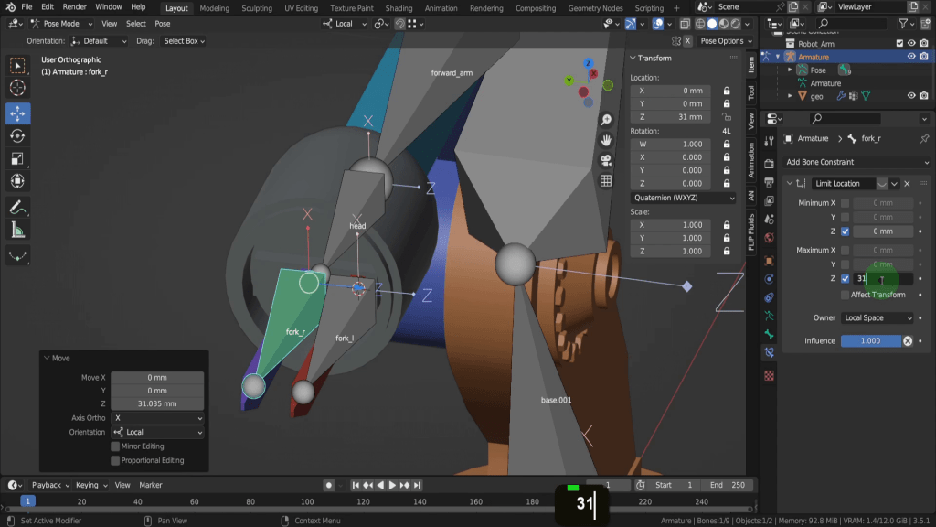
While this is useful can we limit the range somehow. Well that’s where constraints come in handy. Constraints are a powerful feature that allows you to control and limit the movement, rotation, or scaling of objects, bones, or other elements. In the case of the forks here we can use the limit location constraint. This constraint limits the location of an object within a specified range on one or more axes. To add one let’s open the bone constraint properties tab here. Its easy get confused with the object constraints tab but this will apply the constraint to the entire object and not the individual bone. So from the constraint drop down we can choose a limit location.
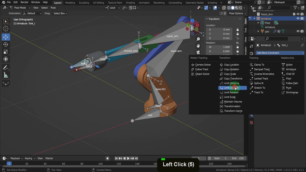
We only want to affect the Z axis so put a check mark to enable both these fields. This is also set to world space so lets switch this to local space. In Blender you’ll will often encounter these two coordinate systems: local space and global space. Understanding the difference between these two spaces is crucial for rigging and animation. Global space refers to the coordinate system of the overall scene in Blender. When you move, rotate, or scale an object in global space, you are changing its properties based on the world’s coordinate system. Local space is specific to each individual object or bone. It represents the coordinate system relative to the object or bone’s origin and orientation. When you move, rotate, or scale an object in local space, you are changing its properties based on its own coordinate system. Here local space allows us manipulate the bone based on its own local orientations. So the values we enter now will be relative to the bones own location and rotation coordinates. Let’s just disable the limit location constrain from a moment and we can see this visually. Right now the minimum we want this to move the bone across is zero. So we don’t need it to go beyond its starting position here on the negative Z. If we select the move gizmo and move this to centre, we don’t want to move beyond centre, which in this case will be 31 on the positive Z. So lets input 31 in the maximum Z field. I tried this earlier so I know 31 works here.
We can switch this back on. So if we drag this manipulator now it’s limited between 0 and 31 along the Z axis.
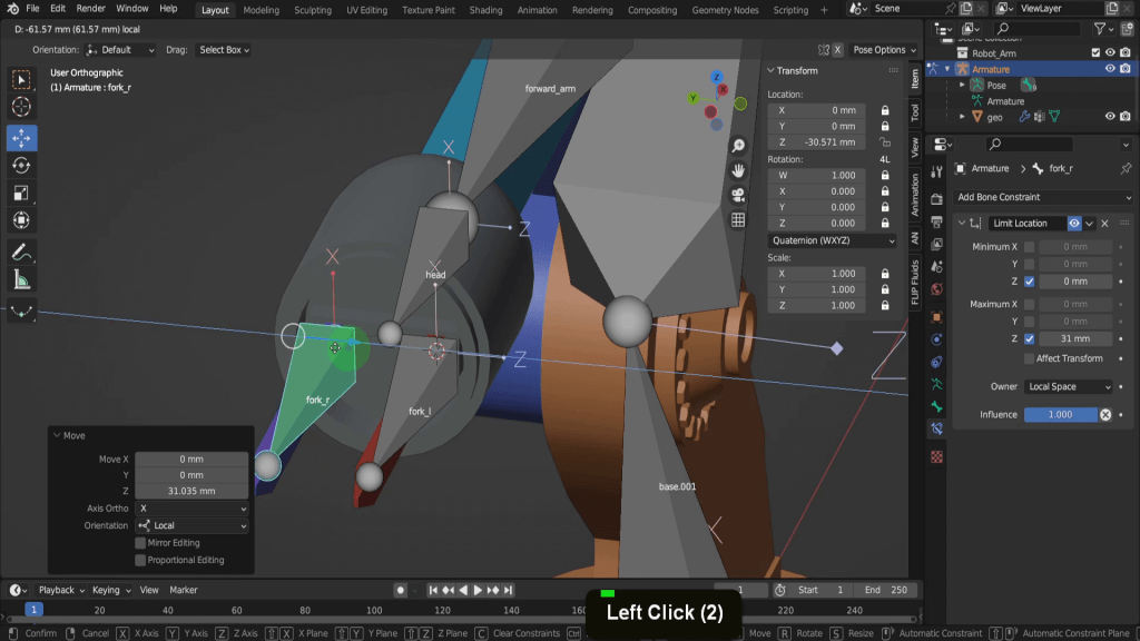
We can do the same thing for the second bone so let’s add a limit location constraint. We can enable the Z maximum and minimum. Switch this to local space. This time the minimum will want to be minus 30 because we’re going into negative X Direction. The maximum can remain at zero. So now if we press G to move each one is constraints between the minimum and maximum values.
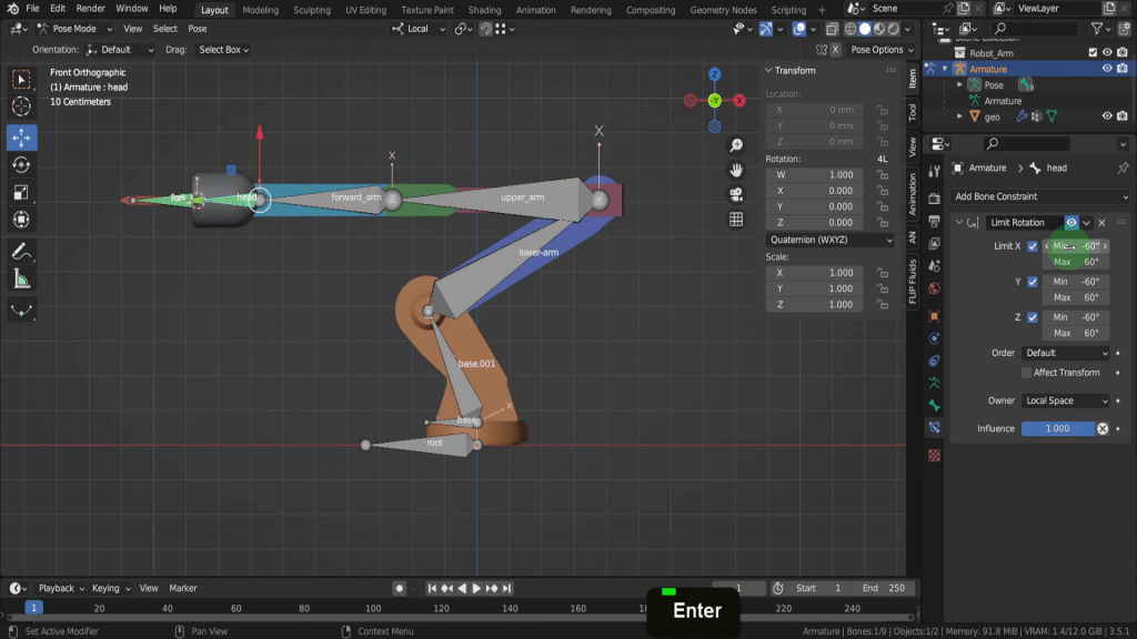
Let’s look at the head bone next. First we can press A to select them all. Press Alt + R, Alt + S and Alt +G to clear out any transforms. Lets come into a front view. Select the head bone. We can add a limit rotation constraint here. Now before we enable any of the axes in the transform X afield let’s click and drag and see what how much we can rotate this back. So about -0.6 looks good here. And if we move this forward maybe 0.6. So let’s right click and bring this back to rest. Let’s enable limit X limit Y and limit Z. We can switch this to local space. So in the minimum X let’s input -60. And in the Max input 60. We can repeat that for the Y and Z using the same values. So in the minimum we can input -60 and in the max input 60. We can do that for both these axes.
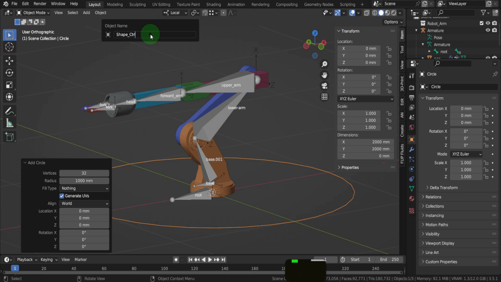
Why not work along and add a constraint to the remaining bones and constraint the movement along the X axis. The next stage to the rigging process are to add rig controls. These are user friendly controls to facilitate the animation workflow. So rather that having these large chunky bones we can add smaller less intrusive shape in their place. Now you can go to great detail in the shape of these controls but for this example we will keep it simple and use a circle. So let’s press Ctrl + Tab and come back to object mode. We can press Shift + S and put the cursor to world origin. Then from the add menu in mesh let’s add a circle. We can press F2 and rename this “Shape_Ctrl”.
Now we need to select the rig again. Press Ctrl + tab and come back into pose mode. Let’s begin with the root bone. Open the bone properties tab and come down to viewport display and expand this. In the custom object field we can click the drop down and choose our shape Ctrl object.
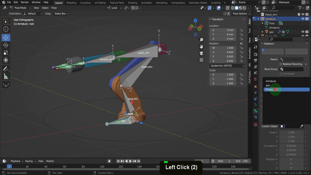
This shape replaces the root bone in the scene. The rotation is at 90 so we can input 90 in the Y rotation field here. This scale to bone length scales the circle to the length of the bone and that works well here.

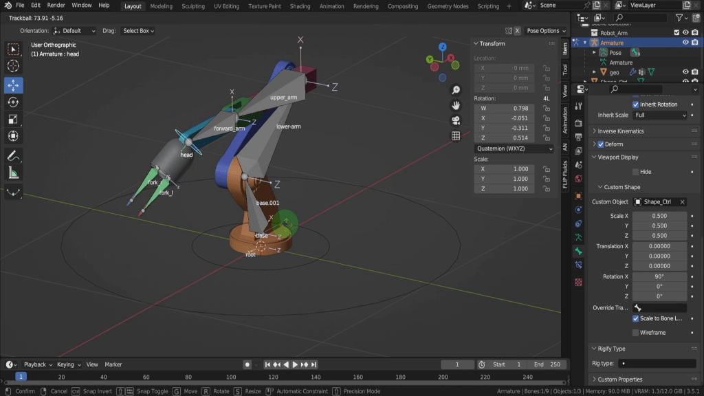
Let’s move on to the base bone. We can do exactly the same thing and choose the shape control object. The defaults wok well here so lets leave those. Lets select the head bone next. Then from custom shape lets choose the shape Ctrl object. This time however in the X rotation field we can input 90 and rotate this around. Click in the XYZ scale we can reduce this to 0.5 and have this a little smaller. So you can see how straight forward it can be to add custom shapes as rig controls to the armature. So if we select the head control and just double tap R this gives us the full control we had with the bone, except its not intrusive.
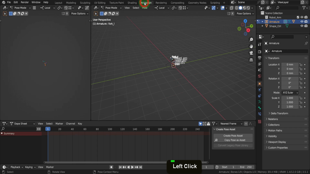
Let’s switch into the animation tab up top here.
We can zoom into the model. In the Outliner let’s hide the visibility of the shape control object. In the object data properties tab let’s uncheck axes. We can also uncheck names just so we have less clutter in the viewport.
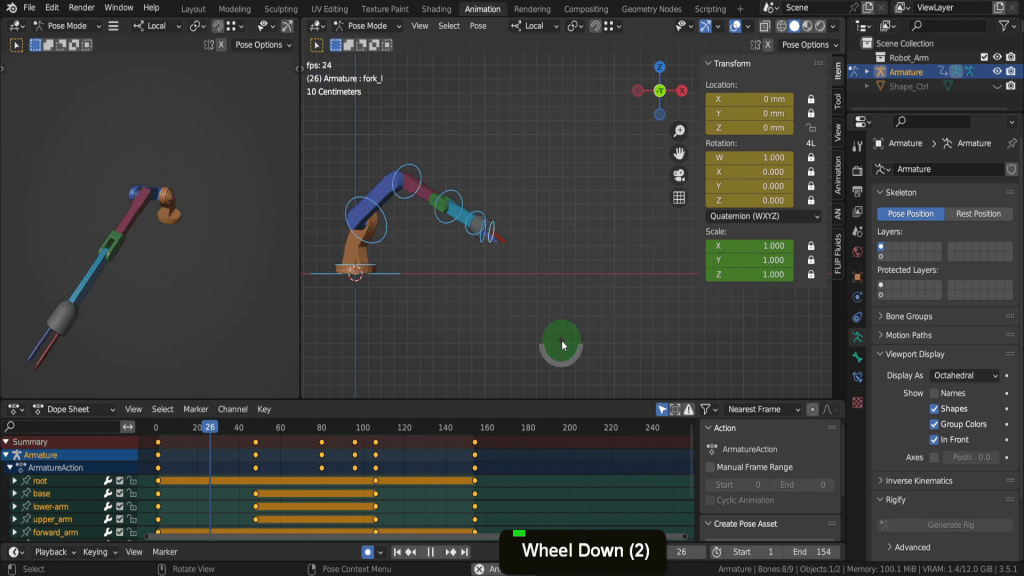
The Animation tab is a dedicated workspace for the animation process. It provides a pre-arranged layout of editors for creating, editing, and previewing animations. On the top right is the 3D Viewport. Below this is the timeline editor. The controls can be used for navigating and setting keyframes during the animation process. Above this is the dope Sheet. This provides a visual representation of keyframes and their timing and allows you edit and adjust keyframes easily. With the cursor in The Dope sheet if you press Ctrl + Tab this toggles you into the graph editor. The graph editor displays and allows you edit animation curves (F-Curves) for more precise control over object properties and interpolation.
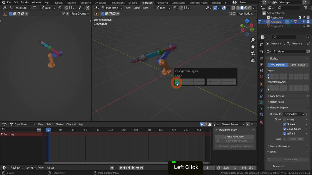
Let’s press Ctrl + tab and switch back to The Dope sheet. Then there is the properties editor and the Outliner. We also have a second 3D view here with some of the scene overlays switched off. Let’s open the object data tab for a moment. Here we have bone layers and we can move this bone base.001 to a hidden layer. So in the scene press M and we can move this to the layer beneath as we won’t be needing it.
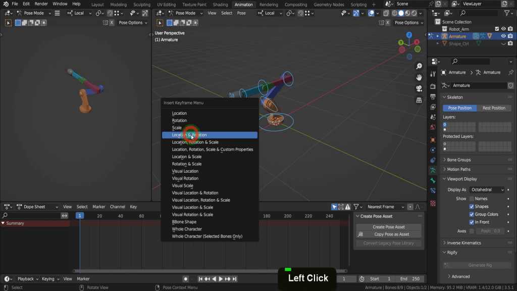
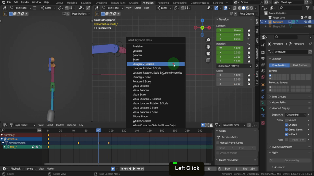
So Let’s Begin and press A to select all the controls. Click the jump to Endpoint button and just make sure the scrubber is back at frame one. Then we can press I and add a location rotation keyframe for all of these bones at this point in time.
Now when animating I usually like to check on auto keying here. Auto Keying is a feature that automatically creates keyframes for bones when their properties, such as location, rotation, or scale, are changed during the animation process. This can significantly speed up the animation workflow, as you do not need to manually insert keyframes each time you move or rotate a bone.
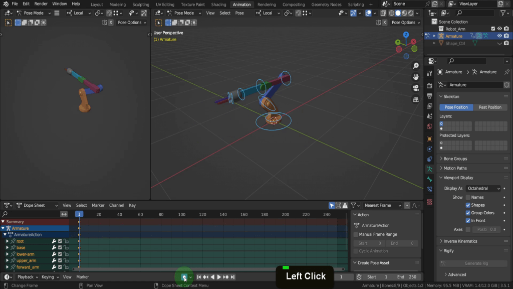
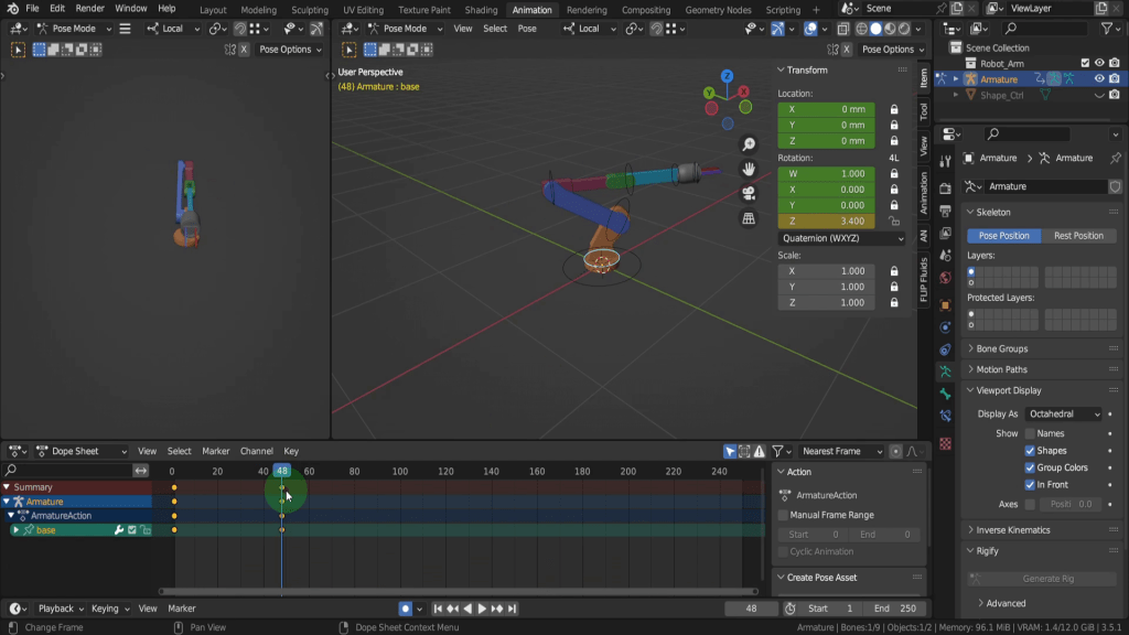
Let’s drag the scrubber onto frame 48 which is two seconds. Two seconds as the default frame rate in a Blender scene is 24fps. We can select the base control. Then on the sidebar in the Z rotation field let’s rotate this around. So maybe 3.4. Now you’ll notice because we have auto keying enabled new keyframe has been added with the change in the controls rotation property. So if we drag back and forth along the time line the arm will rotate back and fourth between those two key frames.
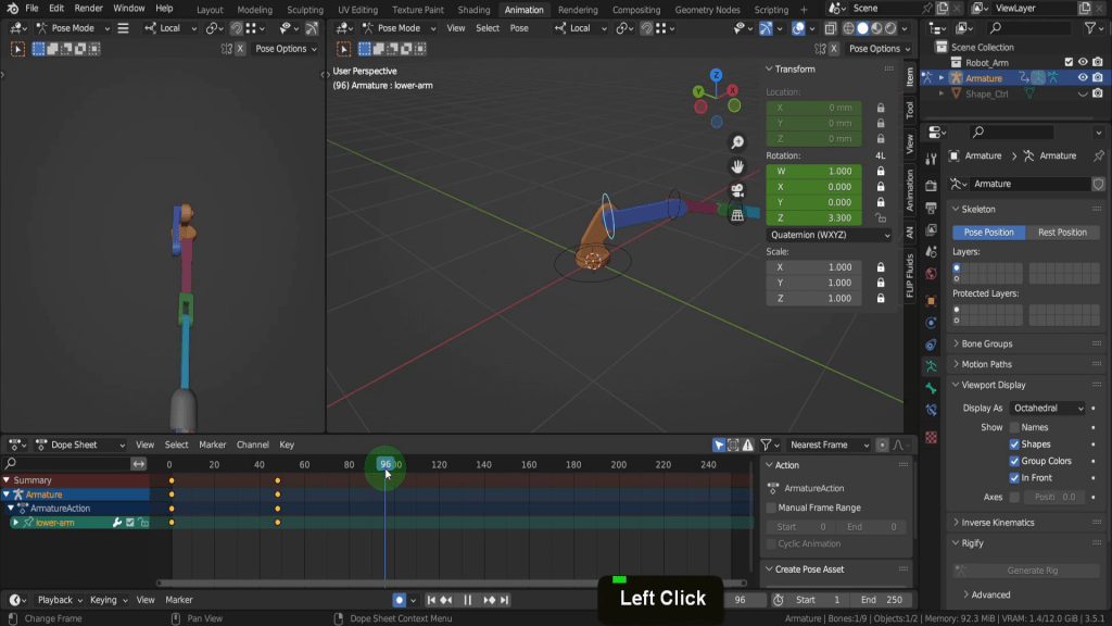
Let’s select the upper arm control. In the X rotation field click and drag and rotate to about -2.4. Next let’s select the lower arm. In the X rotation field we can drag this forward so maybe 3.3.
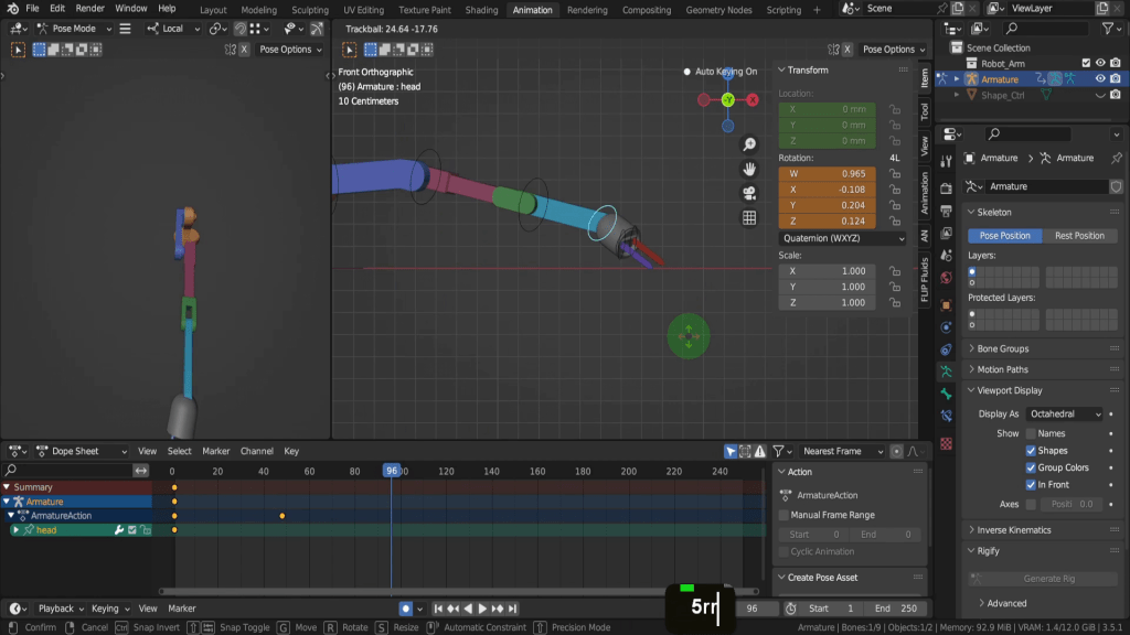
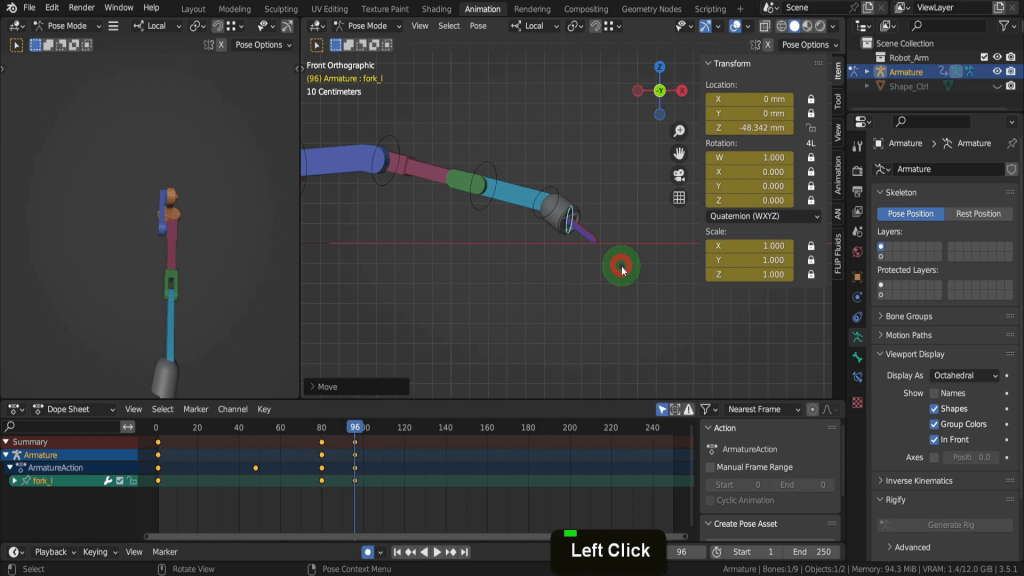
Let’s drag the scrubber on to frame 96 which is four seconds.
Also lets come into a front view. We can select the head next. I’m just going to double tap R and rotate this around a little bit until it comes down to the ground.
Let’s drag the scrubber back to frame 80. Then we can select each of the forks. Press I and add a location rotation keyframe here. Do this for both. We need them open at this stage.
Then if we drag on to frame 96. We can press G and drag these in and until they’re closed.
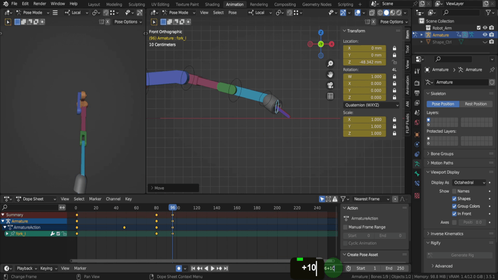
Then let’s click into the current frame field behind 96. We can add a plus and add 10 and press return. That adds 10 frames to the current frame.
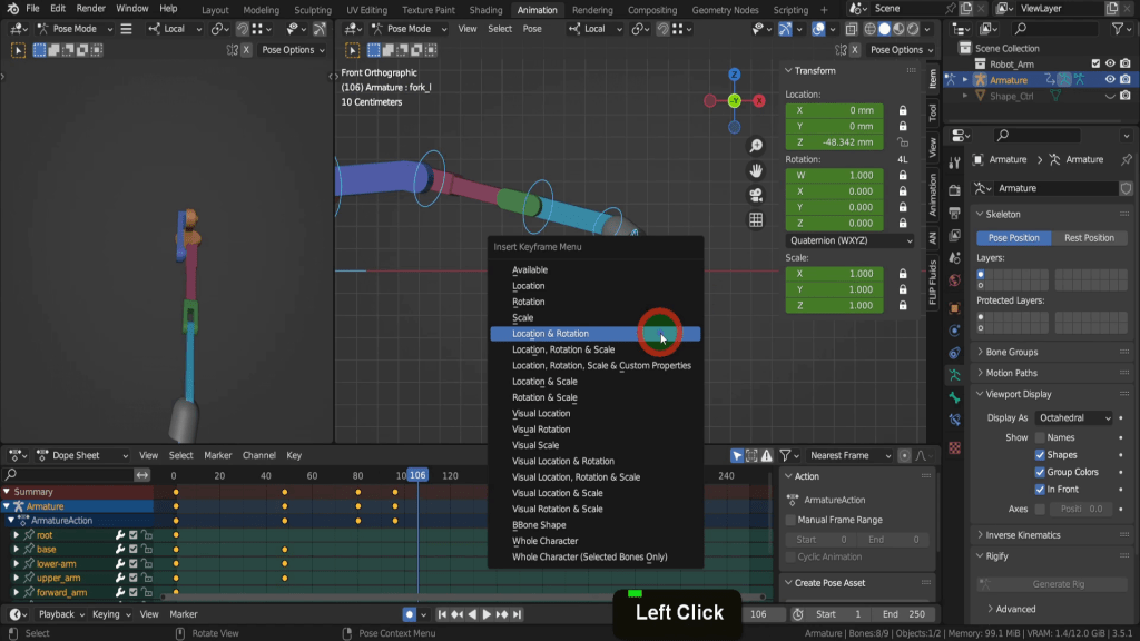
We can press A to select all the bones press I and add a location rotation keyframe to store the values at this point in time.
So now let’s move this on 48 frames, so in the current frame field let’s click at the back of 106. Then if we add a plus, we can input 48. That will add to 106 seconds and bring us up to frame 154. So we can press A to select everything. Press Alt + R and Alt + G to clear out all those transformations.
Let’s press Ctrl + end to bring up the timeline. Then press the space bar to play the animation.
A couple of takeaways when rigging in Blender. Its better rig a character or asset running along the Y axis. This make the symmetrise command available. This asset did begin the correct orientation but during testing somehow got positioned along the X axis. Also we didn’t cover very much with the bone roll but the reason they we at -90 was because of the asset orientation.
