
Introduction
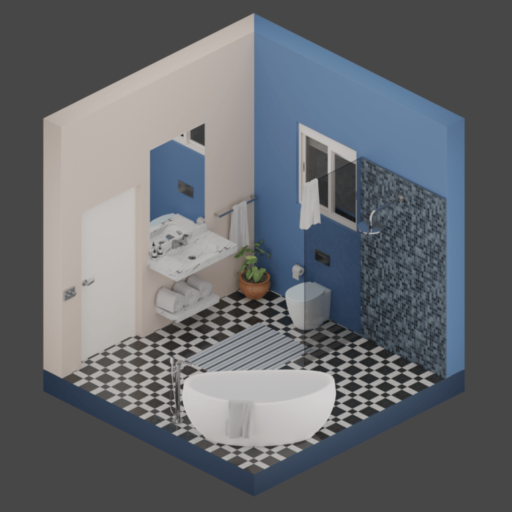
Are you ready to dive into the exciting world of 3D modelling and rendering? In this beginner tutorial, we will guide you step-by-step through the process of creating a captivating isometric bathroom scene using Blender 3D. This will be the finished isometric bathroom scene and I’ll be highlighting the most important aspects of the process. We’ll also explore the fantastic tools, add-ons, the asset browser, with an asset file available on my website, all the way up to rendering. If you want detailed training in Blender check out my courses on Udemy.
Watch the video here:
1. Scene Dimensions
Let’s begin in the default Blender scene and if we press ‘N’, we open the sidebar where we’ll get the cube’s dimensions, which are currently displayed in meters. Everyone has their own preferred units for dimensional display, and my own preference is millimetres. If we open the scene properties tab, in the length setting, this can be changed to millimetres.

It’s important to note that this adjustment simply alters the display of dimensions, effectively representing our cube’s measurements in millimetres. Also If we input values within the scene or apply any modifiers, they will correspondingly be denoted in millimetres. If you plan on exporting to other software applications, it might be beneficial to adjust the scene scale to match external applications. However, since our work will be confined exclusively to Blender, there’s no need to change anything else.
2. Face orientation
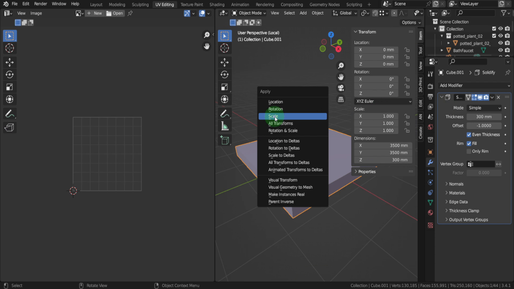
Next we can setup the room and the walls and we can start with the cube. To make this room based off real world sizes lets first scale it up. Its currently 2000mm or 2 metres so lets increase it to 3500, so we can left click into the X dimension field, we can input 3500 here, tab into the Y and input 3500,tab into the Z and input 3700 and we’re good to go.

Bear in mind that any time you scale in object mode, you must apply the changes, so press Ctrl + A and we can apply the scale. Until the scale is applied the mesh data doesn’t update with the change, so anything mesh data related can get unpredictable results. Now we can create the walls so lets tab into edit mode. Lets switch to face select and select the 3 faces that would be blocking the camera. Press X and we can delete these faces.

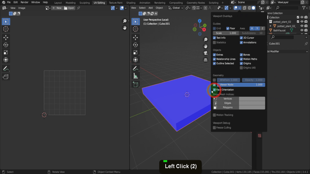
Now while this looks like a quick room one thing to remember when working in 3D applications is face normals, or face orientation. Long story short in the overlays menu if we switch on face orientation the red faces are determined back faces and don’t render, saving compute power.

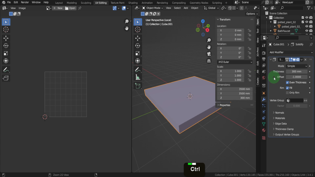
Because these were inward facing on the cube they could remain invisible and nobody would have noticed, but because we destroyed the cube we need to do something about them. That could be to reverse them but a better way is in the modifiers tab here and add a solidify modifier to give them thickness. It fixes the colour issue, as the blue colour means outside faces and the ones that will render. In the thickness field lets input 300 and add some blocks, a cavity and insulation in one go. We can also check on Even Thickness so the mesh keeps it integrity around the corners. Switch off that overlay.

3. Origin Point
Next we can sit the room onto the grid floor as it can be hard work through the grid. So lets come into a front view first. We can also switch to orthographic view so we can see the model straight on.

We need to move this up half the height and 1850 for it to sit on the ground. Press A to select it all. Then just press G Z input 1850 and enter, and in edit mode the origin point of the object remains in place, in this case at the centre of the world.

(Tab back to object mode.) And that can be important for a number of reasons, for scaling, if we wanted to scale this room now it’s going to scale from its origin and makes it very easy resize in place, or having the origin at it base is also important if you were exporting the model.
4. Viewport Shading
Usually when modelling I find it helpful early on to add materials to the objects, as it gives you a clearer visual of each object. Each of the different colours can be unique so lets start adding these in the material tab. If your wall and floor object doesn’t have a material click the plus and add one. We can click and rename this ‘Wall_01’. In the colour swatch we can change this so maybe a dark gray. Then If we hover on the base colour, we can press Ctrl + C to copy that value.

Then lets minimise the tabs in the material editor for a moment. Then if we come down to viewport display. We can drag this up top. Then expand it. We can press Ctrl + V to paste in the copied colour value.

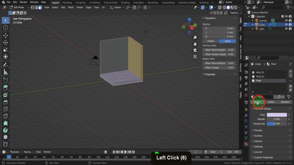
This controls the material colour in the viewport. We want 3 materials in total on this object. One for each wall and one for the floor. So click the plus and add two additional material slots. Then for each slot create a new material. The first we can rename ‘Wall_02’. The second let’s rename this ‘Floor’. Then choose a colour for each of these room elements. Next we need to assign each material to the correct face. So lets tab into edit mode. Select a face in the scene. Then Select wall_02 material, then click and assign the material to that face. Repeat that for the floor and assign the material to the selection.
5. Doors and windows
For the doors and windows we can use an add-on called Archimesh. This needs to be enabled, so let’s press F4 and open preferences. In the add-ons tab scroll down a little and you’ll find it under add-mesh, the Archimesh add-on. Put a check Mark and enable it.

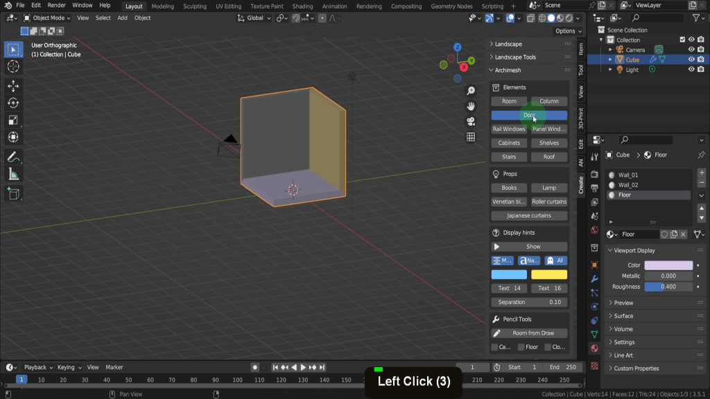
We can close preferences and the add-on will be available in the create tab here, In the Archimesh drop-down. We’ll start with a door so lets click and add one in here.
This gets added at the position of the 3D cursor so let’s select the empty. In the snap menu let’s switch this to Vertex. We can press G Z and snap it to the floor level here. Then press G Y and just drag it in a little bit. To open the door properties we need to select the door frame. The first thing we can do is input 90 and rotate the door around.

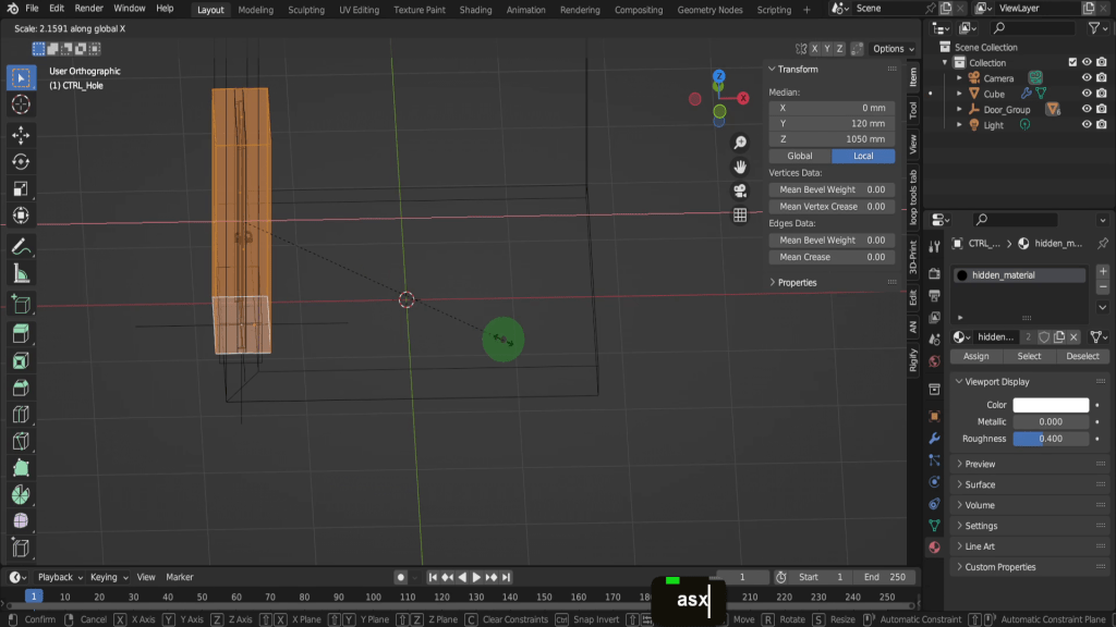
You can set properties like width, height, side it opens on, model and handle type. The default settings for these can be used or can be adjusted at any time as they are parametric. To create a space for the door in a wall, a hole needs to be cut in the wall object. This requires selecting the “empty” object, which is the parent object. Lets press Z and switch to wireframe shading. Then Press G X and drag it back inside the wall. This Ctrl_hole object here is responsible for subtracting the space but its currently not wide enough to completely cut through the wall. So we can select it and tab into edit mode. Press A to select it all. Press S X and scale out beyond the wall both sides.
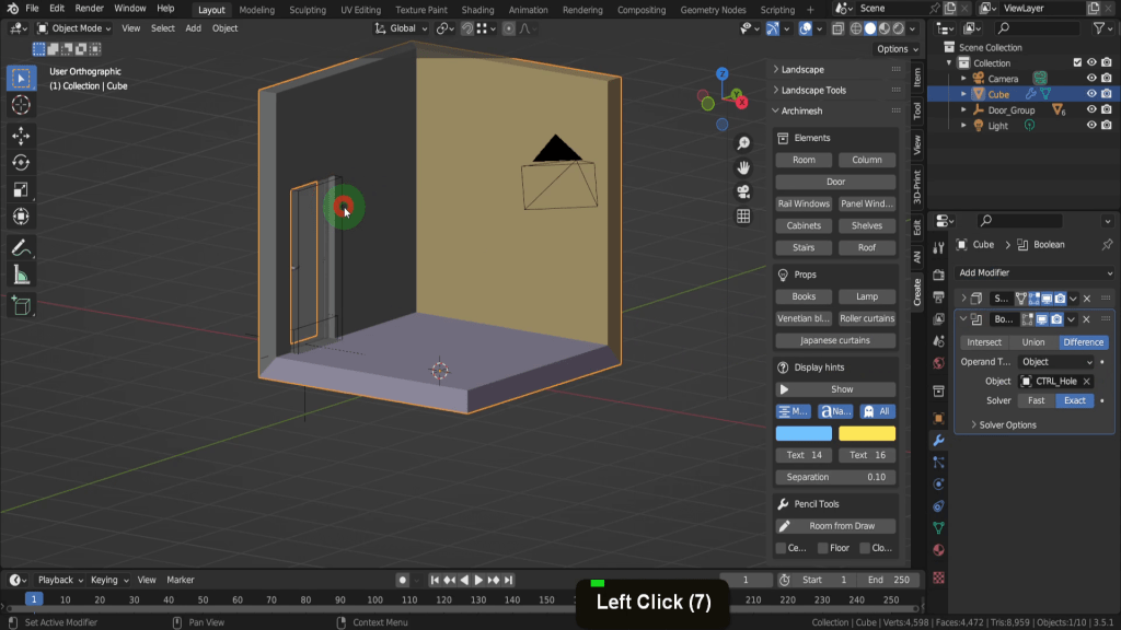
Now let’s tap back to object mode. To cut the hole for the door, a Boolean modifier will need to be added to the wall object. This modifier performs a mathematical operation between two meshes, in this case, subtracting the shape of the empty from the wall object. Select this wall and open the modifiers tab. In the add modifier drop down let’s find and add a boolean modifier. Then we can use the picker and highlight and select this control hole object. That will subtract the shape from the wall and making an opening for the door.
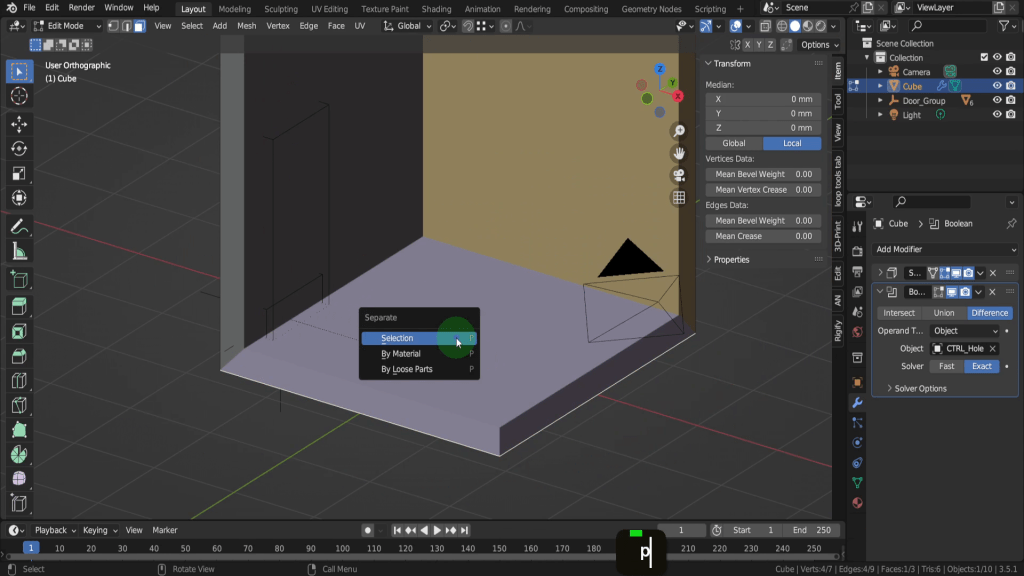
The Boolean operation has also cut into the floor, which is not the intended result. So one fix will be to separate the floor as a separate object. Let’s select the wall again and tap into edit mode. Switch to face select. Then select the bottom face. Press P and separate selection.
Let’s come into a front view and make sure we’re in an Orthographic view. Press Z and switch to wireframe shading. If we switch to Vertex selection. We can drag select the bottom vertices. In the snap menu make sure we’re set to Vertex here.

Then we can press G Z and snap the wall up on top of the floor. Let’s press Z and switch back to solid shading. Tab back to object mode and the floor is now a separate object, so select it. In the modifiers tab remove the boolean modifier and fix the issue.
Window
Next we can add a window into this wall here. The Archimesh add-on has only two window options, but within each window it does offer a great deal of customisation. The base window type we can choose here is the rail window.

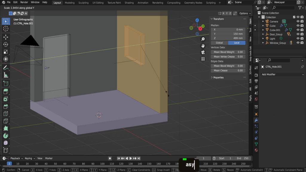
Then use the empty object to position the window at the correct height and location. It can be adjusted at any stage and probably will be as more objects are added. Similar to the door the control hole object will need to be widened to fit the window. To do this we can tab into edit mode. Press A to select it all. Press S Y and scale it along the Y-axis and extend it beyond the wall.
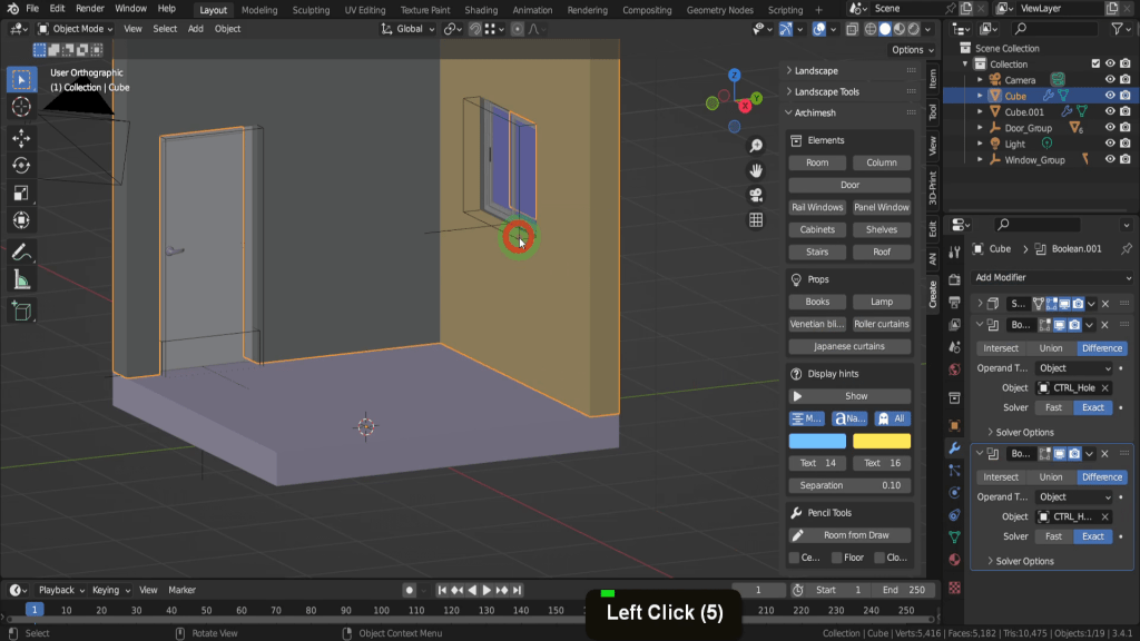
We can tab back now and select the wall. In the modifiers tab we can add another boolean modifier. Then use the picker and select the Ctrl hole object and cut the window into the wall.
6. Isometric Camera Setup
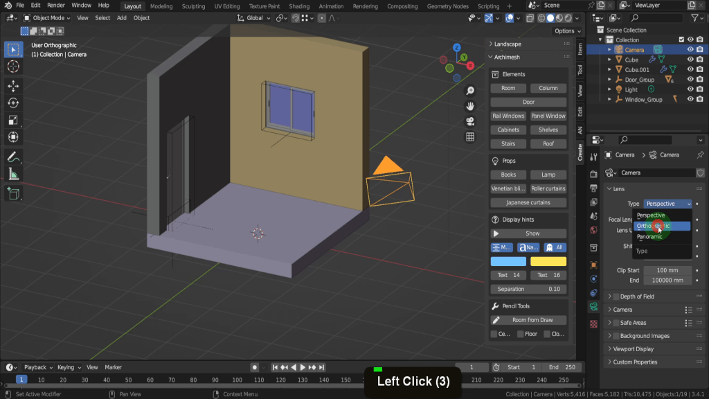
There are many ways to configure the camera in Blender, but in this case, we will focus on establishing an isometric view. This process involves two primary steps: altering the camera angle and changing the camera type to Orthographic. Let’s start by modifying the camera type. To do this lets open the object data properties tab. In the camera type drop down menu, change the option to “Orthographic lens.”
This camera type will help us achieve the isometric perspective we’re aiming for. With the camera type set, the next step is to rotate the camera to the correct angle, and we can do that from the item tab. In the X rotation field lets input 60 degrees. Tab into the Y and input 0 degrees, tab into the Z and input 45 degrees.

We can then enter camera view using this button here.

To frame up the room and find a good distance we need to adjust the Orthographic scale. Just click and drag and get it roughly into position. This can be adjusted at any stage.

Then use the location transforms to frame the view. Finer adjustments can be made later once more objects are added and you get a clearer idea of the scene.

By default, the camera resolution is set to 1920 x 1080 pixels. This can be found and adjusted in the output properties tab. For an isometric view, you might want a square resolution, so adjust the resolution to 1080 x 1080 pixels.
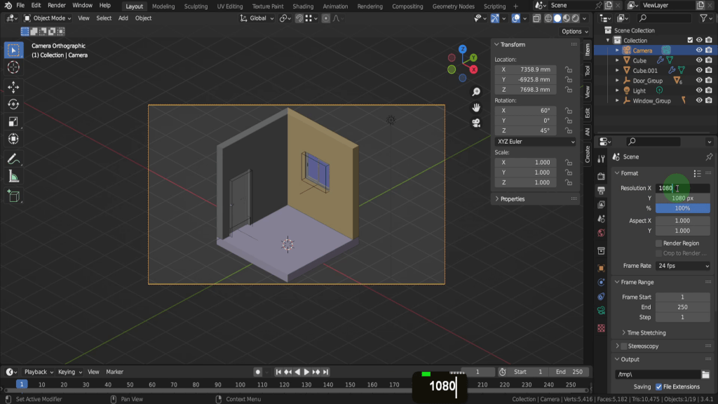
Once you’ve set the resolution, return to the camera properties and adjust the Orthographic scale as needed. In the scene continue aligning and framing the camera.
7. Asset Library (Bathroom Assets)
Next, we’re going to incorporate the bathroom assets into our current scene. You’ll find these assets as a .blend file, conveniently named “Bathroom assets,” on my website. (https://blenderzen.com/assets-2/) So make sure and get that downloaded. Blender includes a built-in feature called the asset library, enabling you to link external .blend files, such as this bathroom assets file, with your ongoing project. This tool facilitates more streamlined and efficient management of multiple assets and objects. If you’re unfamiliar with creating your own asset library in Blender, I suggest you refer to my tutorial, “Set Up an Asset Library in Blender 3D | Step-by-Step Guide for Beginners” (https://www.youtube.com/watch?v=CmTmeFUGtMY) This guide offers a comprehensive, step-by-step instruction on how to establish an asset library and then introduce bathroom assets to your project. Although this might take a bit of time to set up, it’s a worthwhile investment that will definitely pay off in the future. After you’ve set up the asset library, we can switch the timeline editor to an asset library using the editor type drop-down menu.

Increase the window size for a better view. Once you’ve successfully linked your bathroom assets (which can be done through the Preferences menu), they should appear in the asset library, ready to be used in your scene.
8. How to snap and use alignment
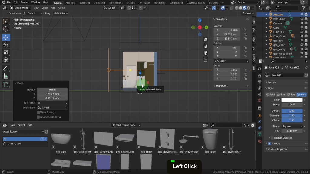
(Bathroom) Integrating assets into your scene is a very straight forward – just drag and drop. A rotation preview for the asset is displayed, and it will situate itself on the surface of the object where it’s dropped.

Once the asset is positioned, activate the transform manipulator tool, which lets you move, scale, or rotate your assets to preferred locations. Next on the list is the vanity. While dragging the asset provides a preview, the orientation might not always be perfect. Most will need correcting orientating but Blender has useful tools for that. A rotation angle becomes visible when you click and drag on the Z rotation axis.

Blender’s snap function comes in handy for precise positioning of assets. In the snap menu, switch the option to ‘Face Project’, and ensure ‘Snap With’ is set to ‘Closest’.

Press ‘G’ and hold ‘Ctrl’ to position the vanity against the wall accurately. The align it along the Z and Y axes to finish placement.

Now, we’ll introduce the mirror and align it with the vanity. Drag the mirror into the scene and position it over the vanity. This also needs to be rotated. Lift this object above first. Then, in the snap menu, switch to vertex. Grab the Z-axis and snap it on top of the Splash Back. For correct alignment, select the mirror and then Shift-select the vanity. Go to ‘Object’, navigate to ‘Transform’, and then ‘Align Objects’.

In the ‘Align Options’ box, align on the Y-axis. This will be ‘Center to Center’ and relative to the active object.

That covers the process of integrating and aligning the assets. Now, I’ll continue to add the remaining assets, and I’ll accelerate this part of the process.
9. External Assets
Let’s explore external resources for more assets. There are numerous sources offering free asset projects, which we can leverage. We can pull up a web browser. One such website is polyhaven which not only provides HDRI and textures but also includes a models section. Although it’s a relatively small collection now, it’s expanding rapidly with high-quality models added regularly. An asset like the Potted Plant would complement the bathroom scene. It’s a ZIP file, so ensure you decompress it and we’ll delve into appending it into the Blender file later. There are various other sources for 3D models online as well, so explore these sites and pick additional models that you’d like to incorporate into the bathroom project. Now, let’s return to Blender.
We can open a file explorer window. Here I have the zipped folder from Poly Haven, which I’ll right-click and choose ‘Extract All’.

After it’s uncompressed, we can access the folder with a double-click. We can examine the content by opening up the blend file. Once it loads, we see a collection called ‘potted_plant_02’, containing three objects: dirt, leaves, and the pot.

We’ll append in these objects from our original Blend file so we can close this blend file and return to our original project.
To use the append function to incorporate these assets; go to ‘File’ and select ‘Append’.
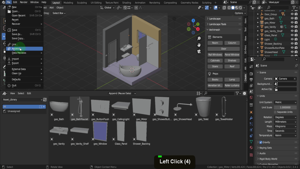
Navigate to the potted_plant file and double-click it to access it, and then the ‘Collection’. Here, we can select the ‘potted_plant_02’ collection and append it into our file.

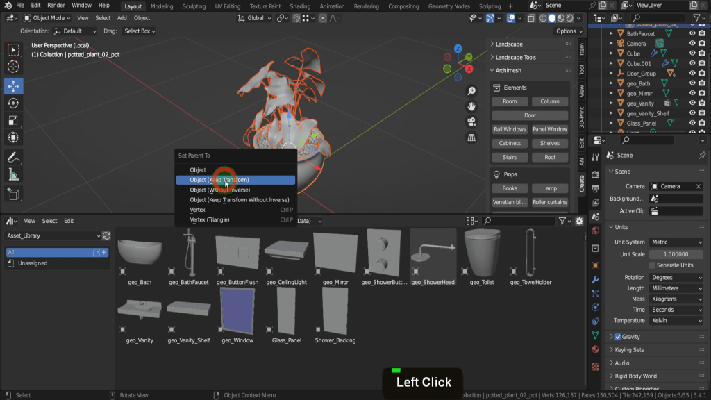
These objects appear selected in the scene. Press the forward slash key to isolate them. Currently, these objects move independently, so we’ll Shift-select the leaves, dirt, and finally the pot. By pressing Ctrl + P, we can set the parent to the object while keeping the transform.
Now, if we select the pot and move it, all objects follow along. After returning to the Global view, we can move this around the scene and position it accordingly.
That’s how you add external assets from blend files to your scene. For FBX assets, it’s as simple as going to ‘File’ and selecting ‘Import FBX’. Now, I’ll speed through the process of adding more assets to my scene.
10. External Materials
That brings us onto materials. We can open a web browser for this. The first site I’ve looked up is PolyHaven, which we’ve used earlier for the potted plant asset. This platform also offers texture maps that might be useful for some of your materials. Although they’re more appropriate for exterior finishes, it’s always worthwhile to explore.
The next site on the list is Ambient CG. Here, you can peruse all their assets. Their offerings are more suitable for interior finishes, so you can pick a variety of texture maps for the materials you think will be required.
Lastly, we have blendermada. This site provides a range of procedural materials available for download. So, you can browse these texture libraries and download any texture maps that might be useful for your project.
I’ll quickly gather several materials for the project I think I will need so try do the same and I’ll speed up this process. Then we can return to Blender.
11. UV Unwrapping
Models or meshes that utilize texture maps in their materials will require UV unwrapping; otherwise, the materials will appear distorted. On the other hand, models using procedural materials don’t necessarily require a UV map. Let’s use the floor as an example to demonstrate how to unwrap an object.
With the floor selected, we’ll switch to the UV editing tab.
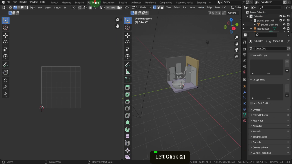
We can press the forward slash key to isolate this object. This action puts us in edit mode, but let’s tab back to object mode for a moment.
In the modifiers tab, this object gains its thickness from the solidify modifier. Before we apply the solidify modifier, let’s examine the object scale.
By pressing ‘N’, we can open up the sidebar. Before applying modifiers or UV mapping, ensure your scale is uniform; otherwise, you won’t achieve accurate results. Press Ctrl + A for the apply menu and apply if you have a non-uniform scale.
Now, we can apply the modifier – hover over the solidify modifier and press Ctrl + A to apply it.
The final step before UV unwrapping is to check the face orientation. Access the overlays menu and turn on ‘Face Orientation’.
We want to confirm that we have the face normals correctly oriented; the blue colour indicates they are forward-facing. Let’s disable the orientation overlay now.
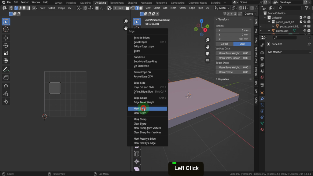
We can tab into edit mode. This will be a straightforward UV unwrap, so let’s switch to Edge selection. Select the top four edges and split this section away. Press Ctrl + E to open the Edge menu and mark a seam.
Next, select the four short edges around this section. Press Ctrl + E again and mark another seam.
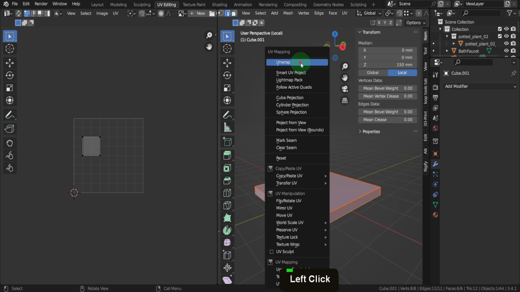
Finally, press ‘A’ to select the entire mesh, then ‘U’ and choose ‘Unwrap’ from the options that appear.
12. Texture Resolution
In the process of UV mapping, it’s crucial to maintain consistent texture resolution across all models. This ensures the quality of texture remains uniform in the final render. While you can make adjustments based on size and significance of objects, for our purposes, we’ll strive for consistency. Luckily, Blender is equipped with an add-on called ‘Magic UV’ that does the calculations for us, eliminating guesswork.
Press F4, open preferences, and navigate to the ‘Add-ons’ tab. Type ‘Magic UV’ into the search bar and enable the add-on by checking the box when it appears. If you’re interested, expand the add-on information to find a documentation link that will guide you through the utility’s features.

For now, we’ll stick with the default settings and close the preferences window. The Magic UV add-on can be found in the sidebar under the edit tab.
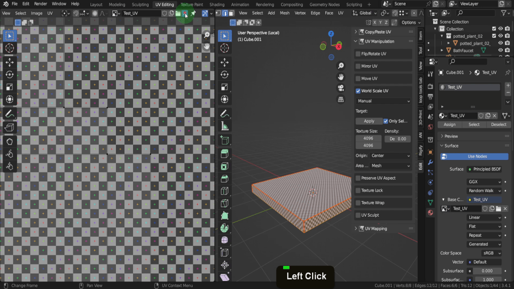
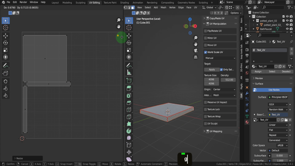
You’ll need to be in edit mode to access the Magic UV’s three menus. Let’s unfold the UV manipulation tab. Enable ‘World Scale UV’, which allows the add-on to calculate and apply the density based on our input. Ensure the setting is on manual, so we can enter the values. In the texture size field, input ‘4096 x 4096’, which will be our standard texture size.

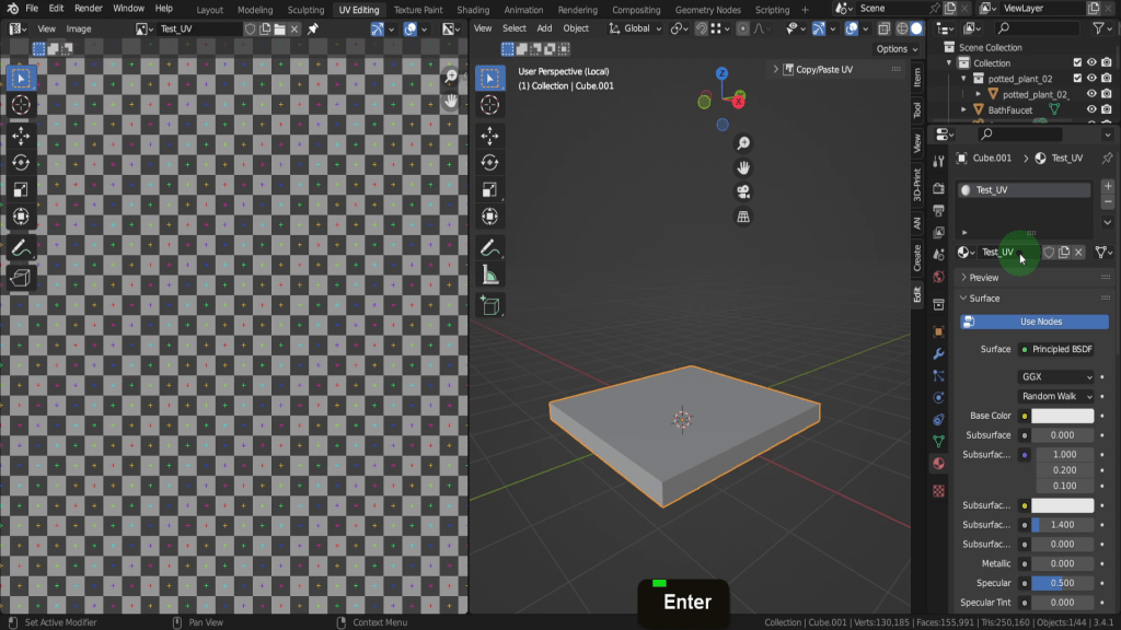
We can also create a test texture to visualize the resolution. In the image editor, click ‘New’ and rename the image texture ‘Test UV’. Set the image resolution to ‘4096 x 4096’ and switch the generated type to UV grid.

Now, return to the material tab. We’ll need to be in object mode for the next step so tab back. Then let’s remove all the material slots form the floor. Now create a new material. Rename this Text_UV.
Switch back to edit mode. Add an image texture slot to the back of the base color and search for ‘Test UV’ from the drop-down list.

In the scene, press Z and switch to material preview to display the texture on our object. In the UV editor, remove the texture so we can see the UVs.
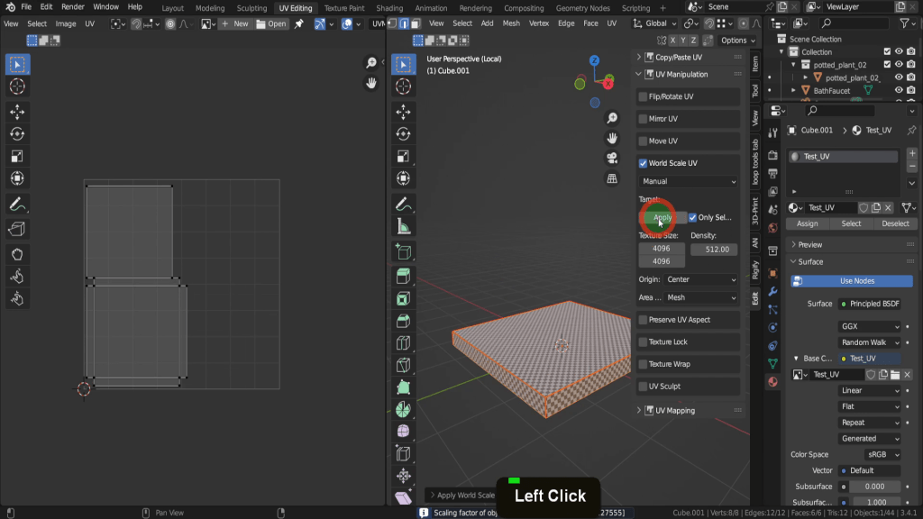
We can now adjust the values in the ‘Target density’ field – let’s test with ‘512’. Make sure all vertices are selected before clicking ‘Apply’ to update the UV scale.
13. Maximising Texture Space
On examining the UVs, we’ll notice that the bottom face and the two back faces on this object, which aren’t visible, are taking up a significant amount of space. By selecting these faces on the model, we can maximize our texture space. In the UV editor, enable ‘UV Sync Selection’ which allows you to select faces and keep UVs visible regardless of selection.

Scale these faces down significantly as they don’t need to occupy much space. Move this minimized area to the top.
Invert the selection by pressing Ctrl + I. Back in the add-on, increase the density value to 1024 and apply this.

From the UV menu, choose ‘Pack Islands’, which may slightly reduce their scale for a better fit, and that will be fine.

Switch back to the layout tab now. That will be the process of UV mapping the objects so I can speed up the remaining UV mapping. Every object is now UV unwrapped with the ‘Test UV’ material applied and the density value updated. The result ensures a consistent texture resolution across all objects for the final render. Remember, individual adjustments can be made as necessary. So for example the walls are the only UV’s I reduced because of their size. If you needed these the same resolution you could separate them, but because I’ll be using a paint material this resolution will be fine.

14. Materials
Let’s now apply some materials to the objects. Starting with the floor, we’ll use tile textures sourced from AmbientCG. Switch to the shading tab. First, remove the test material from the floor and create a new one, which we’ll rename ‘Floor’.
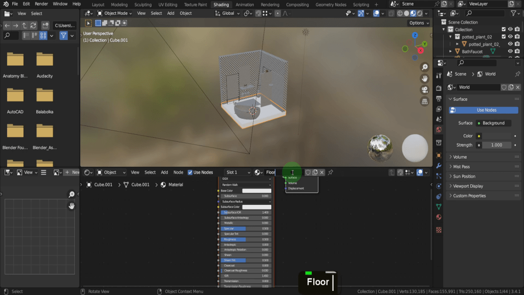
You can add the texture set using a shortcut provided by the Node Wrangler add-on. If you don’t already have it enabled, go to Preferences, search for ‘Node’, and enable the Node Wrangler. This add-on allows you to use the ‘Add Principled Setup’ feature found in the Node Wrangler tab in the sidebar (press N to open).
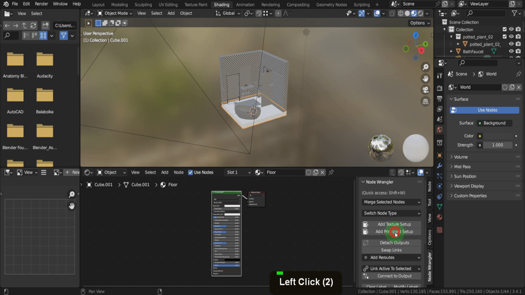
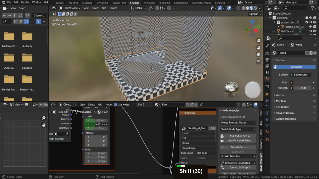
Navigate to your textures folder and Ctrl-select the texture maps you want to include (Colour, Displacement, NormalGL, Roughness).

Choose ‘Principled Texture Setup’, and these will automatically connect to the principled node. You may need to adjust the scale – in this case, input 15 into the X, Y, Z fields. Adjust the X and Y locations so the texture aligns with the edge of the floor.
The floor material will also cover the front two edges, but let’s apply a different material there. In edit mode, select these two faces, assign them to a new slot, and create a new material named ‘Floor Edge’. Use the Picker to select a dark colour on the floor for this material and reduce the Roughness value to zero.

Procedural Material
For the bathtub, let’s use a procedural material as an example. Zoom into the bath and rename its material ‘Bath’. In the Shader editor, make the screen full (Ctrl + space). Leave the base colour as the default off-white. Increase the subsurface to 0.1, Specular to one, and Roughness to 0.5. Maximize Clear coat to 1 for a good material look.

So let’s return to previous. If I rotate around here that looks pretty good. That will be the process for the remaining materials I’ll quickly add a mixture of procedural and texture based materials and I can speed this up.
15. Lighting
Now for the lighting and for this I’m going to use some area lights. So let’s first press Shift + S and put the cursor to world origin. Then from the add menu in lights let’s add an area.

This gets added at the 3D cursor so let’s press G, Z and drag this up above the room. In the light properties let’s increase the power to a 100W. In the size field, click and drag up and increase to cover the top of the room.

Lets make a duplicate so press Shift + D and we can right click. In the Y location field let’s input 90°. If we come into a front view we can press G and drag this over in front of the room here and position that out front. Lets repeat that select the top one again. Press Shift + D and we can right click. This time in the X rotation field let’s input 90. Then if we come into a side view we can press G and drag this over in front of the room.
So now let’s jump back into camera view.
16. Render
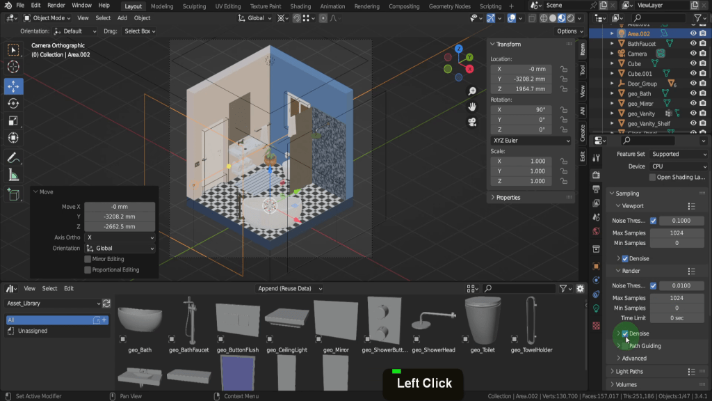
We’re ready to render. Open the render properties tab and confirm that the render engine is set to Cycles.

In the ‘Sampling’ section, increase the max samples to 1024. Enable denoise and help reduce noise in the final image.
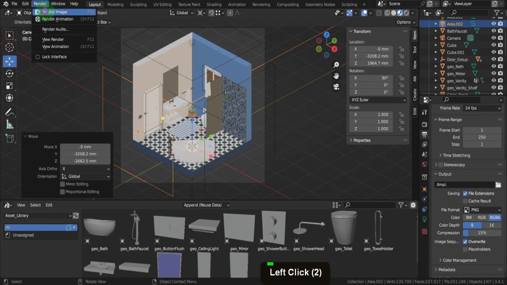
The rest of the settings should be fine, so let’s open the output properties tab. We previously set the resolution to 1080×1080, which is large enough for our purposes, but you can increase or decrease if necessary. Make sure the file format is PNG.

From the render menu, click ‘Render Image’.
This will take a few minutes, so I’ll speed this up. This render serves as a great starting point for developing this interior room. Adding additional models and adjusting the lights can further enhance the scene. But for now, hopefully, it gives you some ideas for creating this type of render. If you’re happy with the result, save the image.
Conclusion:
Congratulations! You’ve successfully created a stunning isometric bathroom scene in Blender 3D. By following this beginner tutorial, you’ve gained valuable skills in scene setup, asset management, material application, and lighting techniques. Keep exploring the possibilities, and let your imagination run wild in your future 3D projects!
